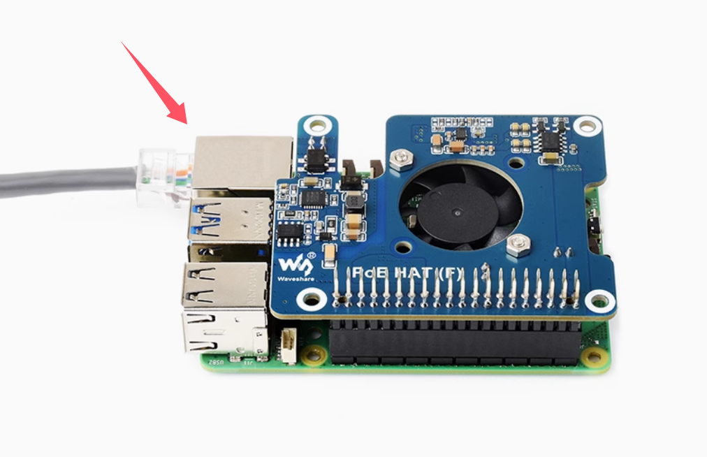
Walnut Pi 2B Peripheral Assembly
After learning about the Walnut Pi hardware in the previous section, we now have a general understanding of it. However, the Walnut Pi board alone cannot function—it requires certain essential peripherals such as a power supply, keyboard, mouse, and display. This section provides a detailed guide on assembling the Walnut Pi 2B peripherals.
MicroSD Card
The MicroSD card needs to be pre-loaded with the operating system, which will be covered in detail in the next section on system and software. This section only covers installation. A MicroSD card of 16GB or larger is recommended.
Gently insert the MicroSD card all the way in the direction shown below.
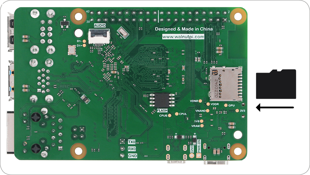
If you need to remove the SD card, simply pull it out.
Do not insert or remove the SD card while the board is powered on.
Keyboard and Mouse
Walnut Pi supports both wired and wireless keyboards and mice.
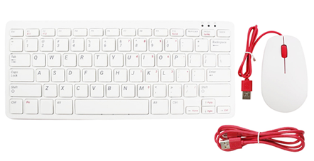
Wired Keyboard & Mouse
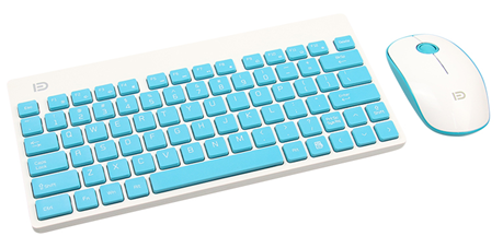
Wireless Keyboard & Mouse
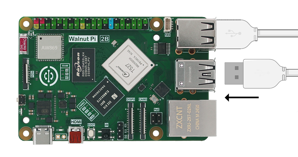
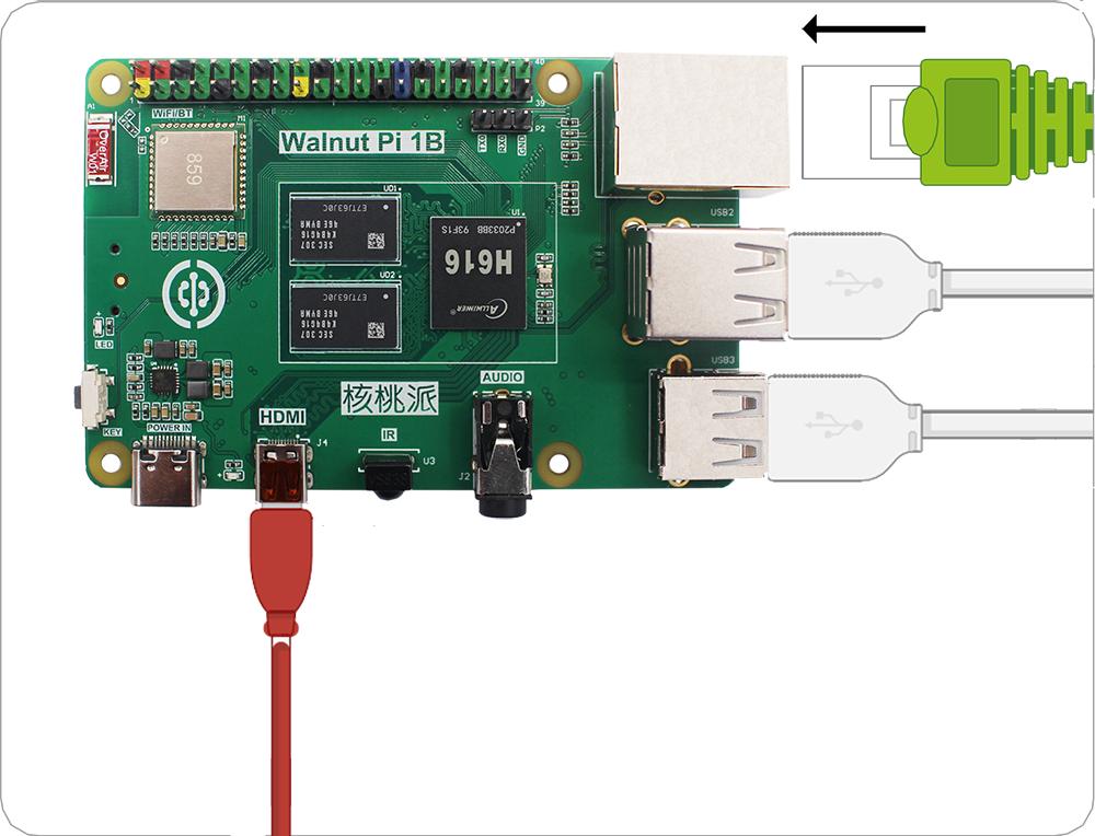
Connect the keyboard and mouse to the USB ports. The installation method is the same for both wired and wireless USB devices. Normally, USB insertion and removal should not require excessive force—if it feels stuck, you may have reversed the orientation. Check that the USB connector is facing the correct direction.
Display
Most computer monitors and TVs come with an HDMI port.
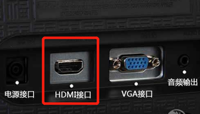
Use a micro HDMI to HDMI cable to directly display the Walnut Pi video output.
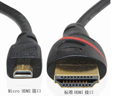
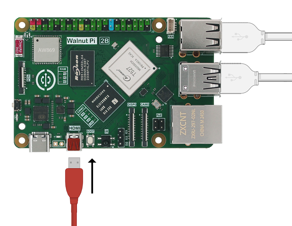
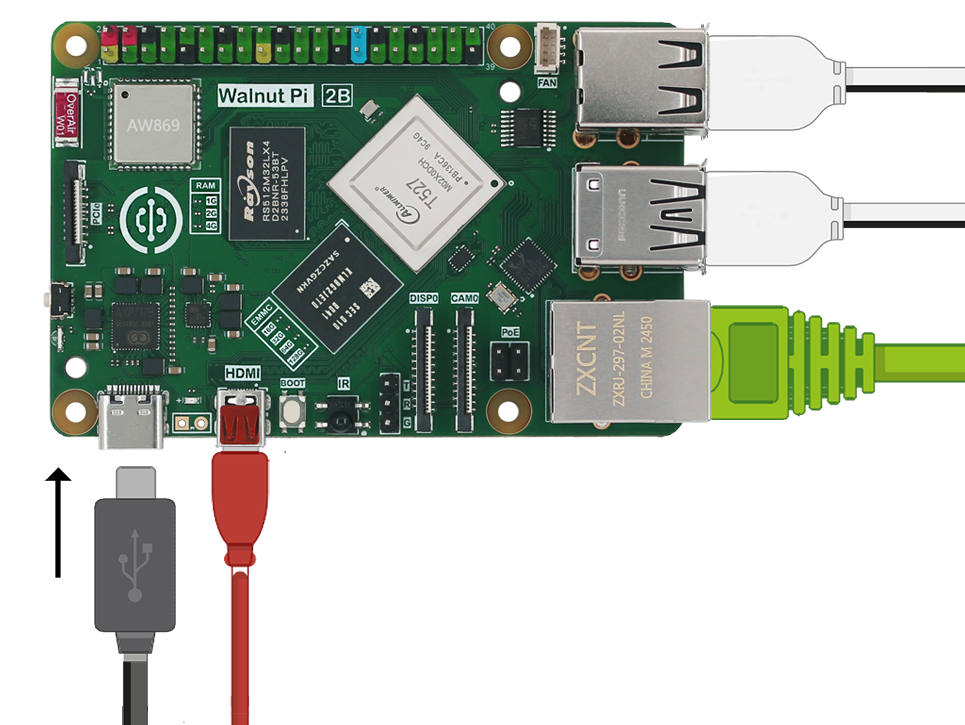
Connect the smaller micro HDMI end to the Walnut Pi (the port near the Type-C power port), and the other end to your display. If your display has multiple input ports, you may need to switch the input source—this depends on your specific display.
Ethernet Cable (Optional)
You can connect the Walnut Pi to a network via Ethernet or WiFi. WiFi is the usual choice, and Walnut Pi supports 5G WiFi. This section focuses on the Ethernet connection method. Insert the cable into the Ethernet port with the plastic clip facing down until you hear a click. The other end of the cable typically connects to any available LAN port on a router, network hub, or switch. To remove the cable, squeeze the plastic clip inward toward the plug and gently slide the cable out.
Audio (Optional)
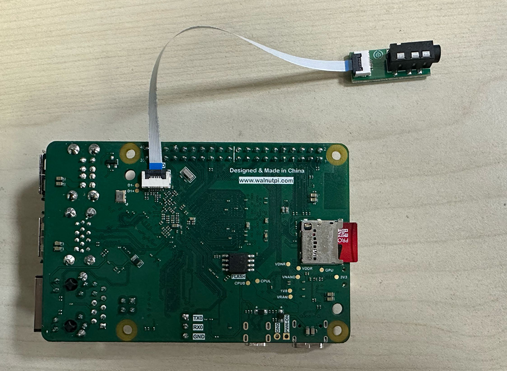
The back of the Walnut Pi 2B has an audio FPC connector, which can be adapted to a 3.5mm audio jack (the common headphone jack) using an adapter board. This can be used to connect headphones or speakers for louder sound output.

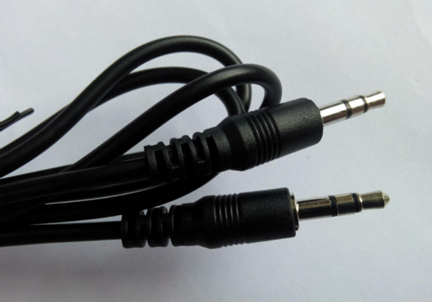
Walnut Pi can also output audio through HDMI.
Active Cooling Fan
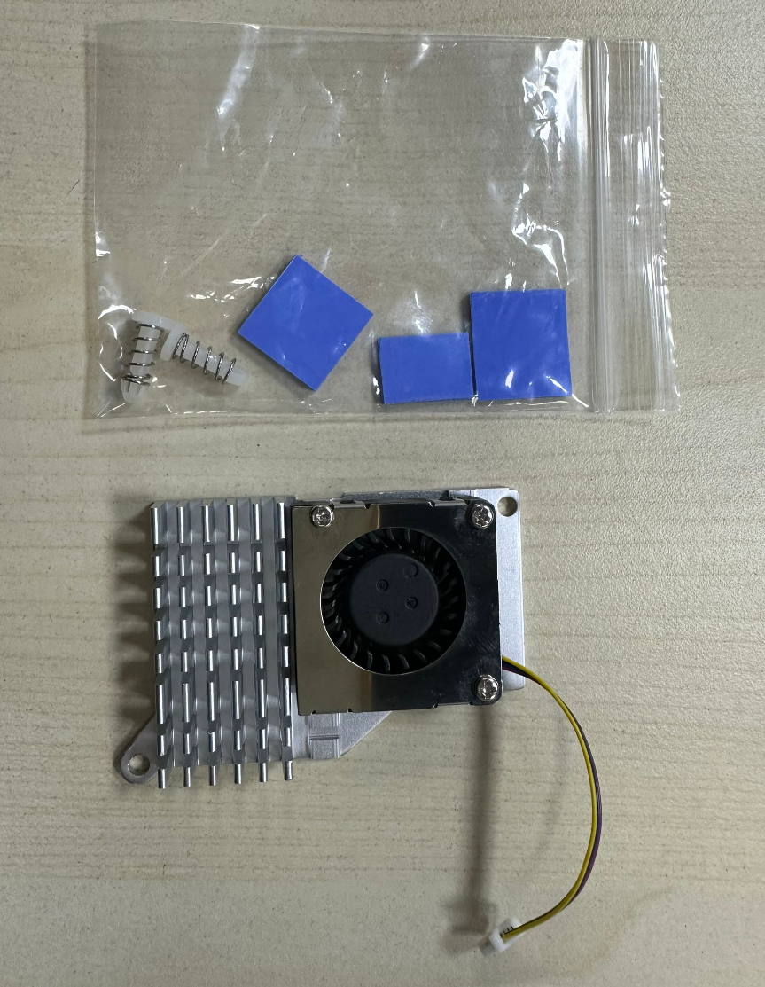
The active cooling fan helps the Walnut Pi board dissipate heat effectively, ensuring stable operation especially in high-temperature environments. The Walnut Pi 2B automatically adjusts the fan speed based on the chip temperature.
Installation steps:
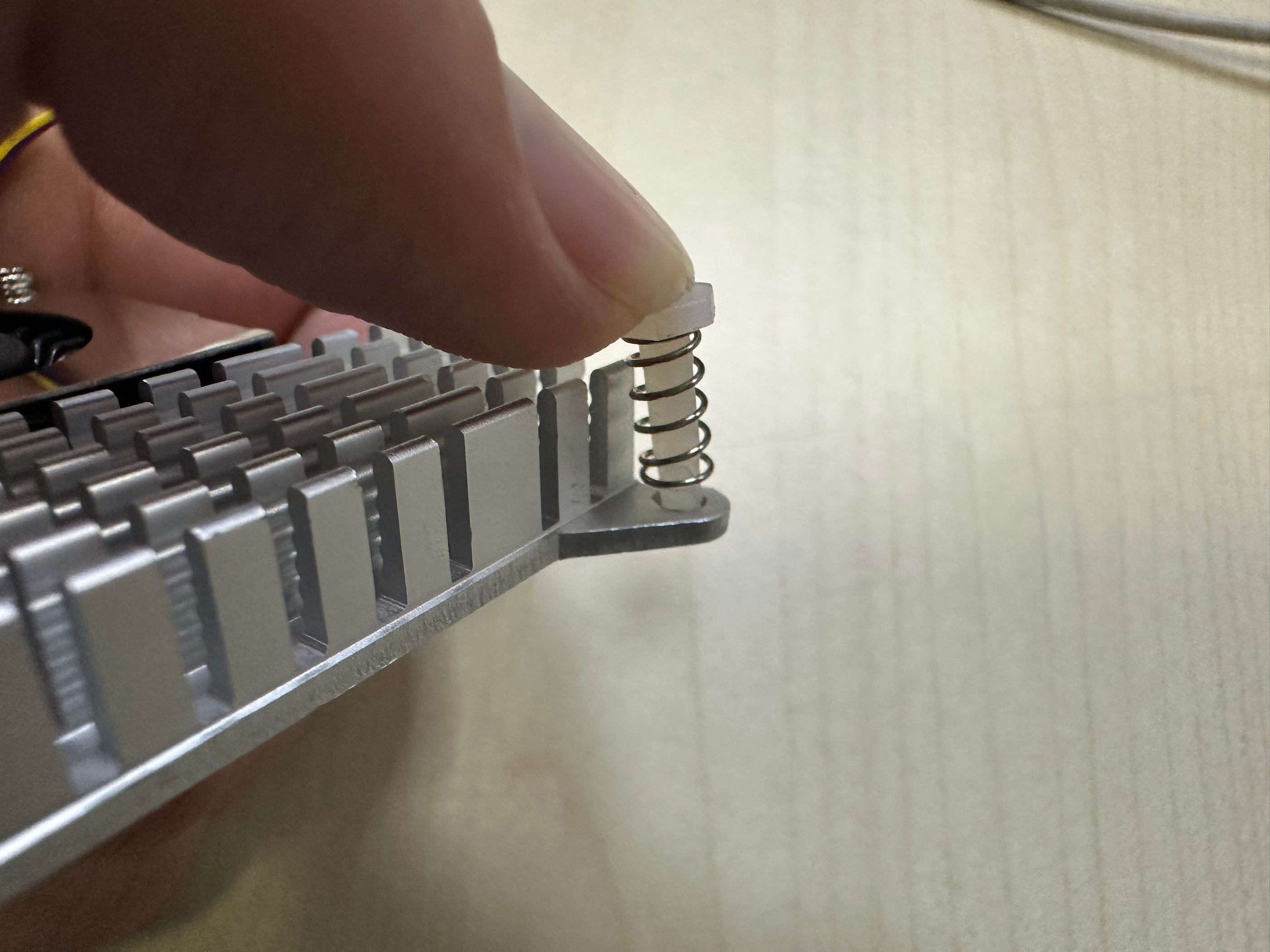
Insert the 2 spring-loaded mounting pins into the cooling fan holes as shown below:
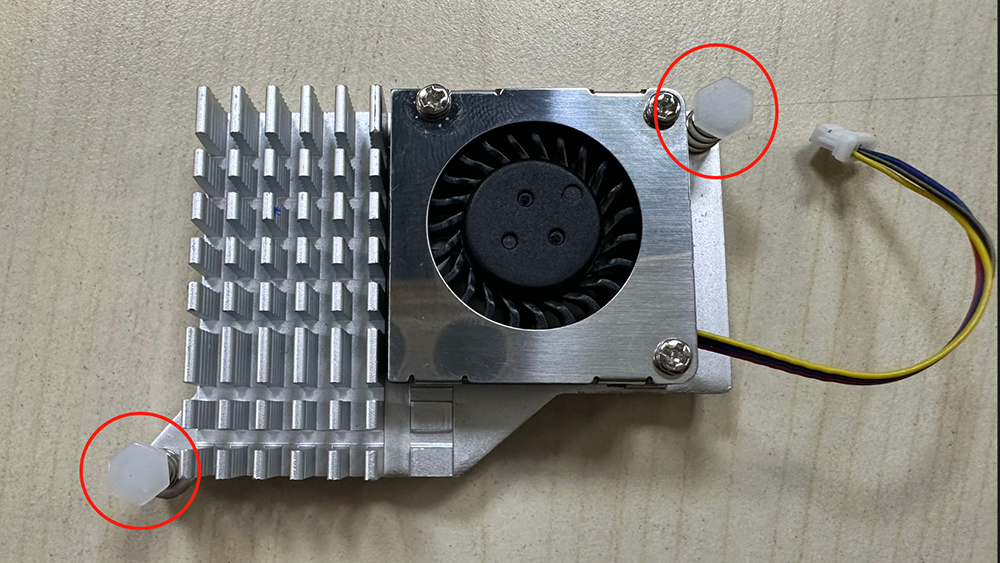
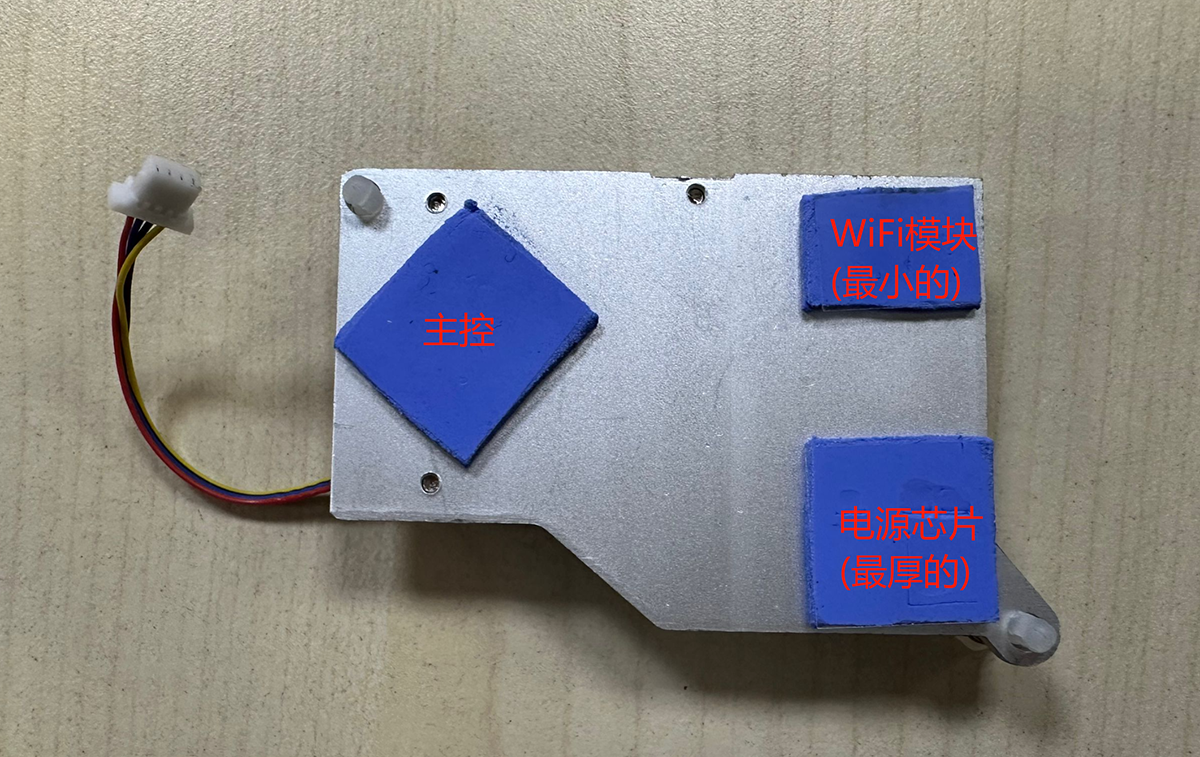
Peel off one side of the protective film from each of the 3 included thermal pads and place them as shown below. Approximate positioning is fine—slight deviations are acceptable.
- The thickest pad goes on the bottom-right corner (for PMIC cooling)
- The smallest pad goes on the top-right corner (for WiFi module cooling)
- The remaining pad goes on the left (for T527 chipset cooling)
Peel off the remaining protective film from the thermal pads, then align and insert the fan mounting pins into the 2 heat sink holes on the Walnut Pi.
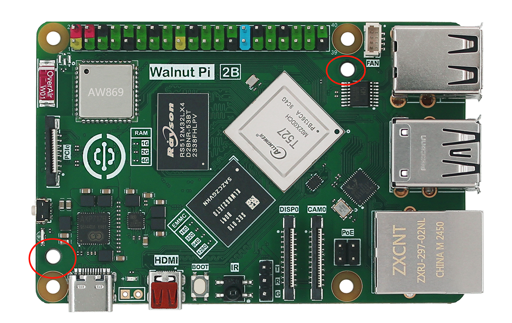
The clips will lock automatically.
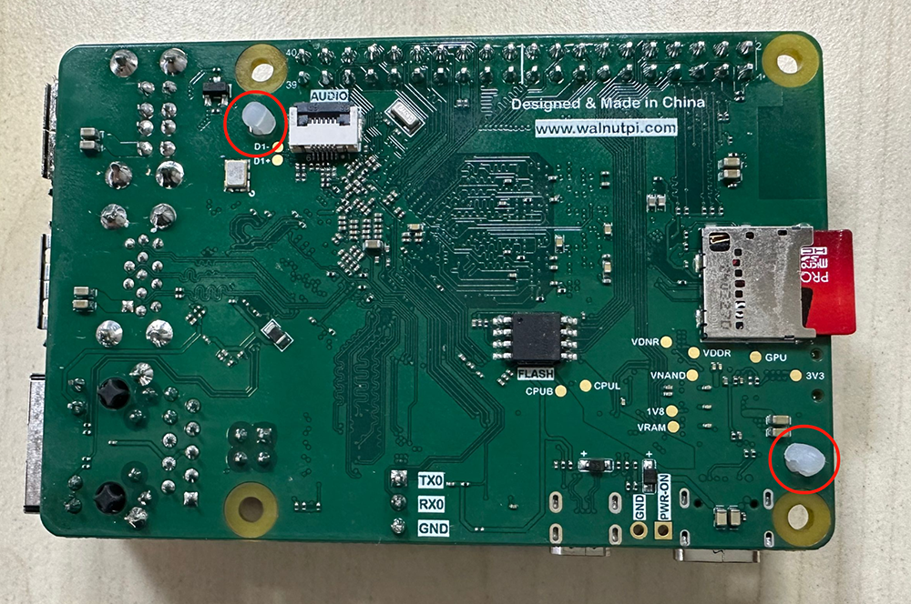
Finally, plug the 4-pin connector into the Walnut Pi 2B fan header.
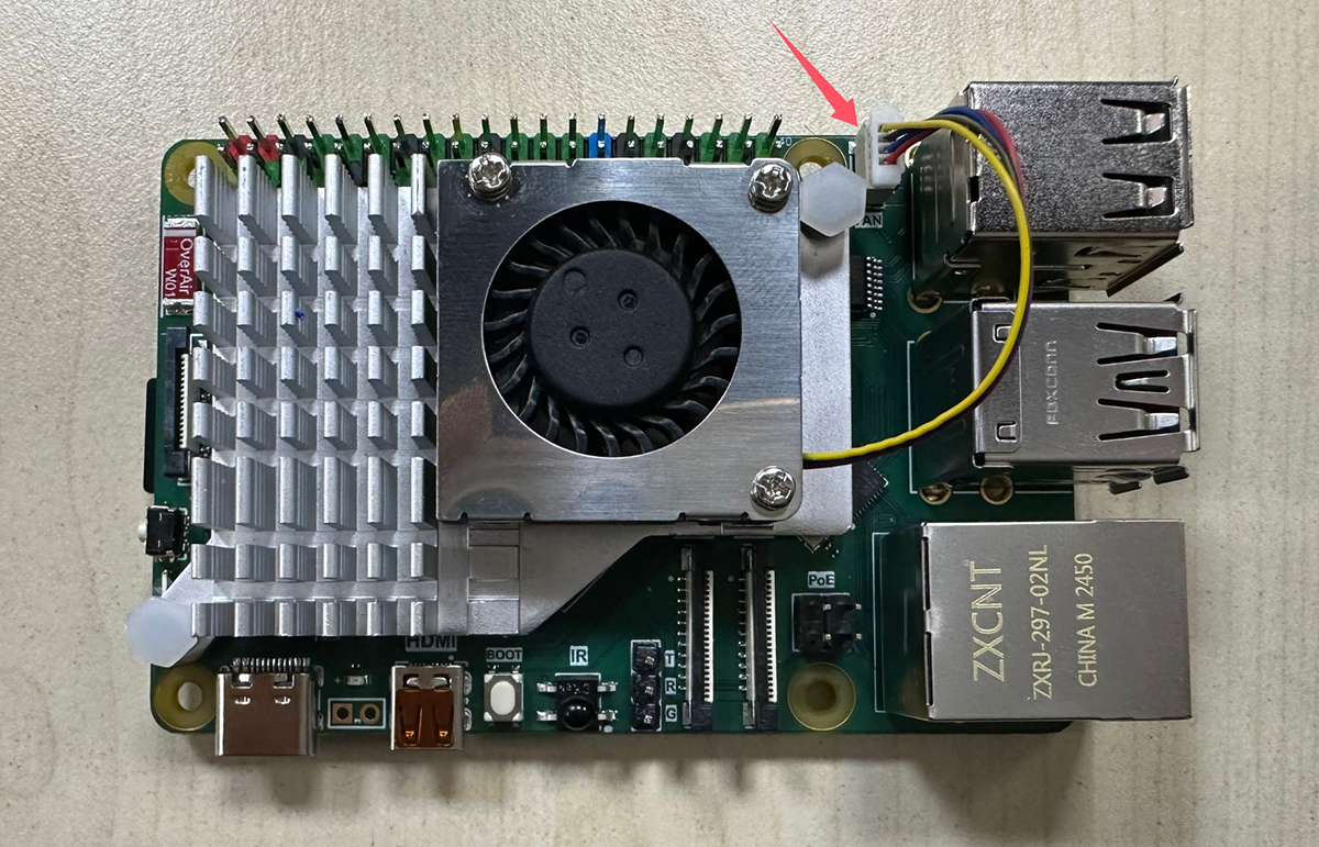
Use tweezers or small pliers if you need to remove it. Be careful not to damage the components around the spring mounting posts.
Case
In addition to the acrylic base plate, you can directly assemble the Walnut Pi 2B case. (Cases compatible with Raspberry Pi 5 on the market can generally be used as well.)
Here we use the officially recommended Walnut Pi case:
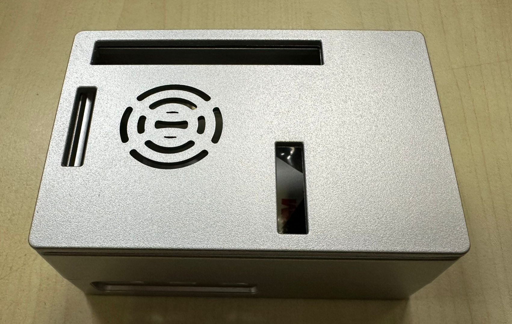
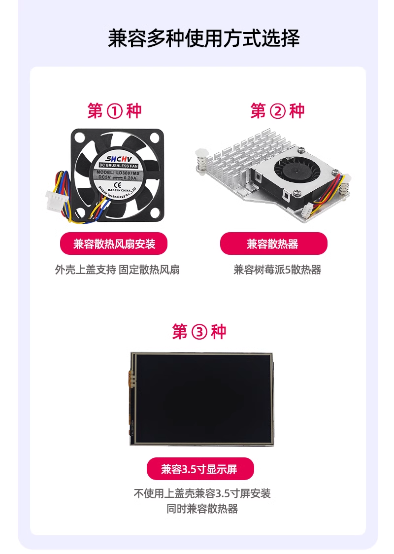
Supports multiple usage modes:
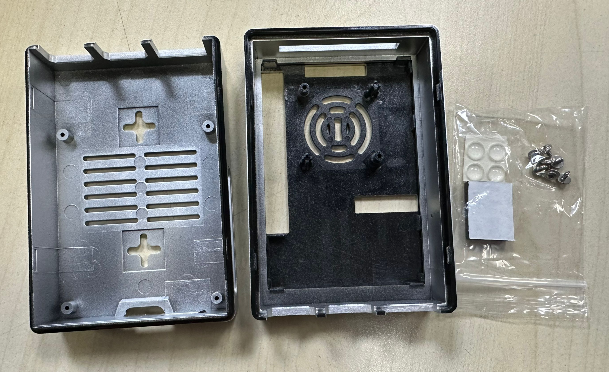
Disassemble the case by splitting it from the middle:
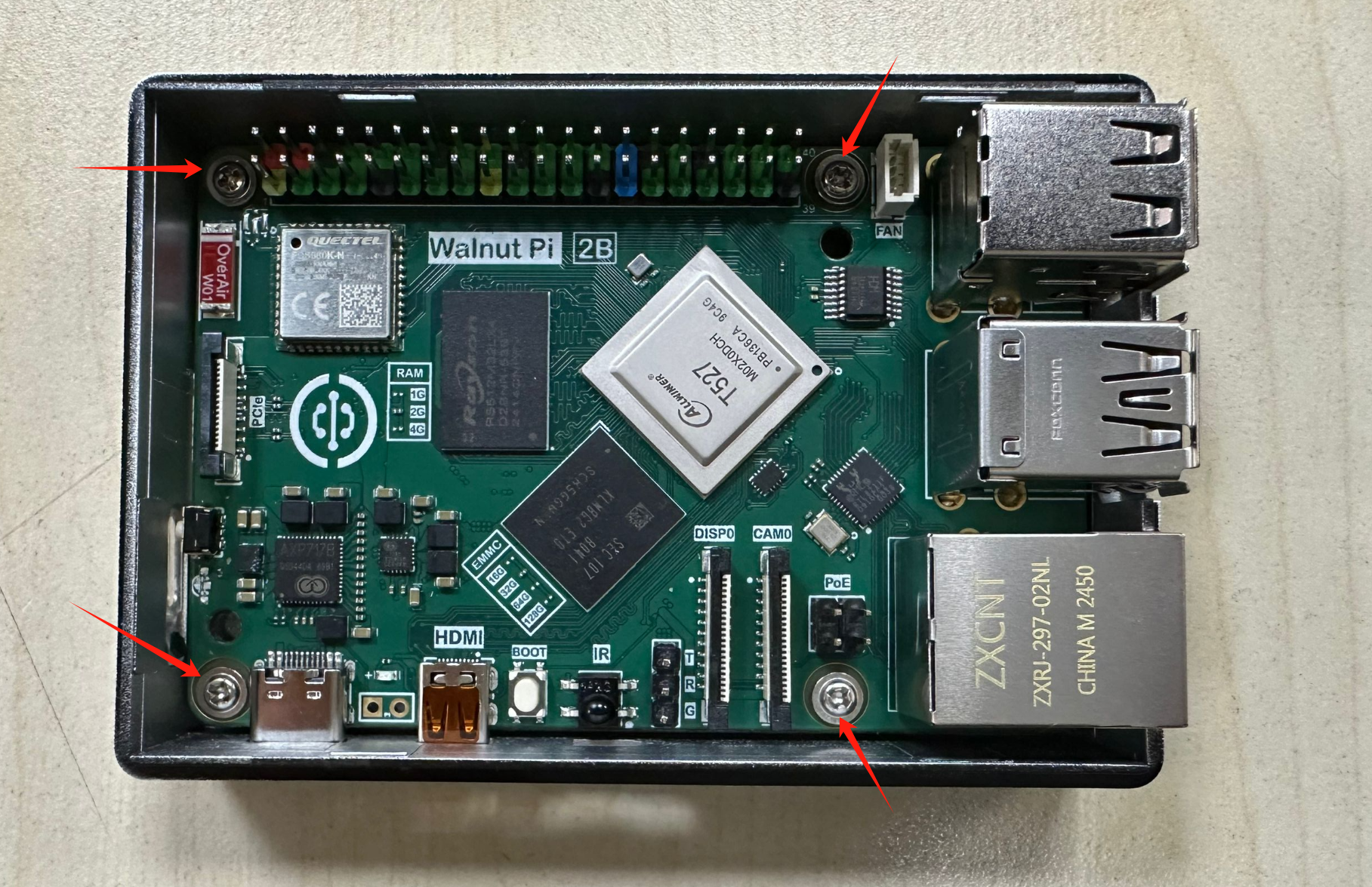
Place the Walnut Pi 2B inside the case and tighten the 4 alignment holes with the included screws.
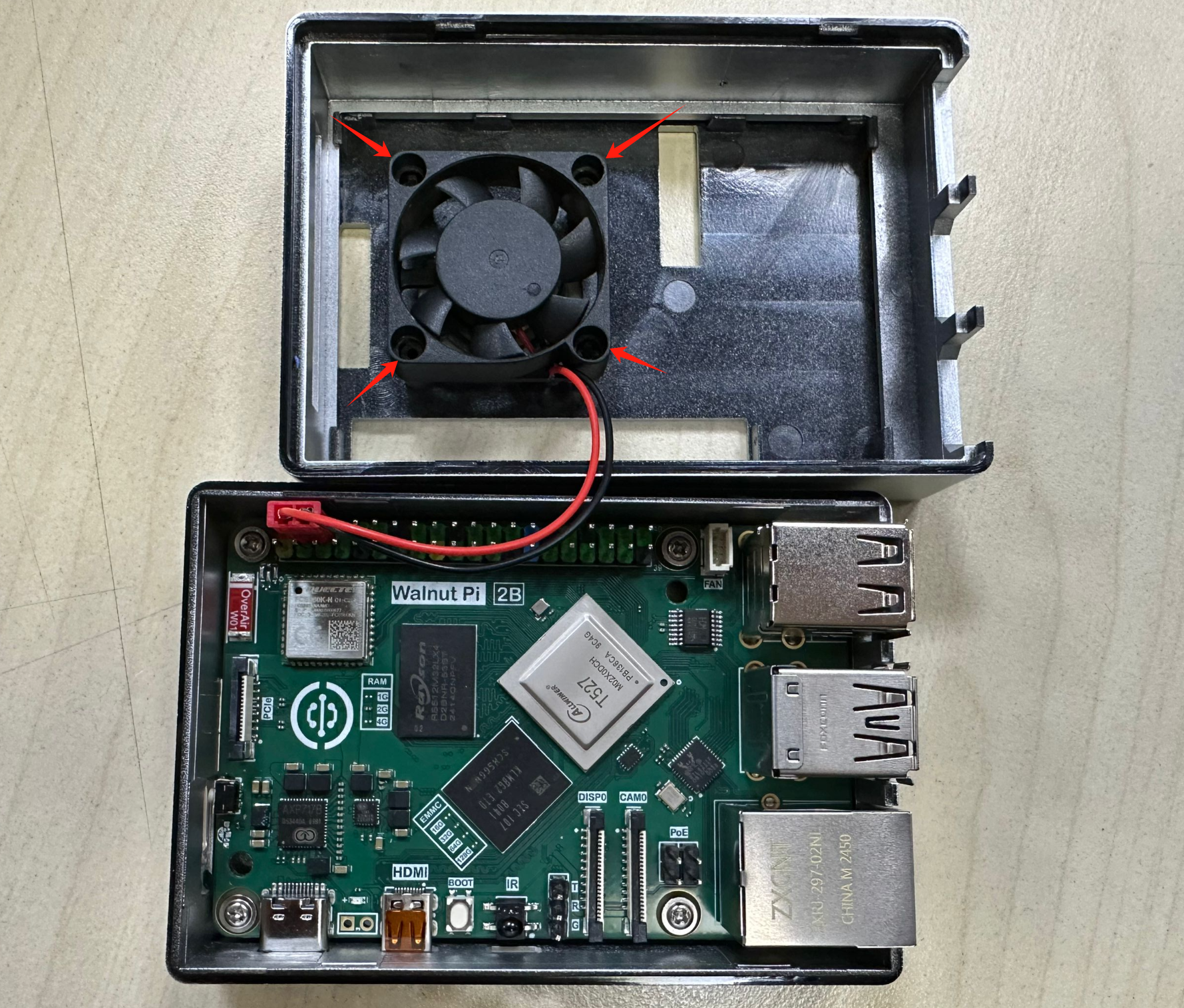
Supports an external 3007 fan—simply insert it into the top cover mounting posts as shown below.
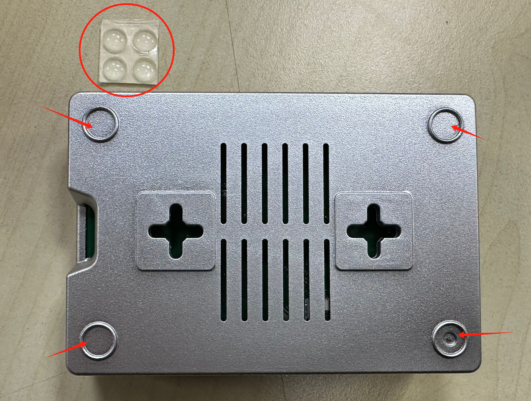
Attach the included anti-slip pads to the bottom:
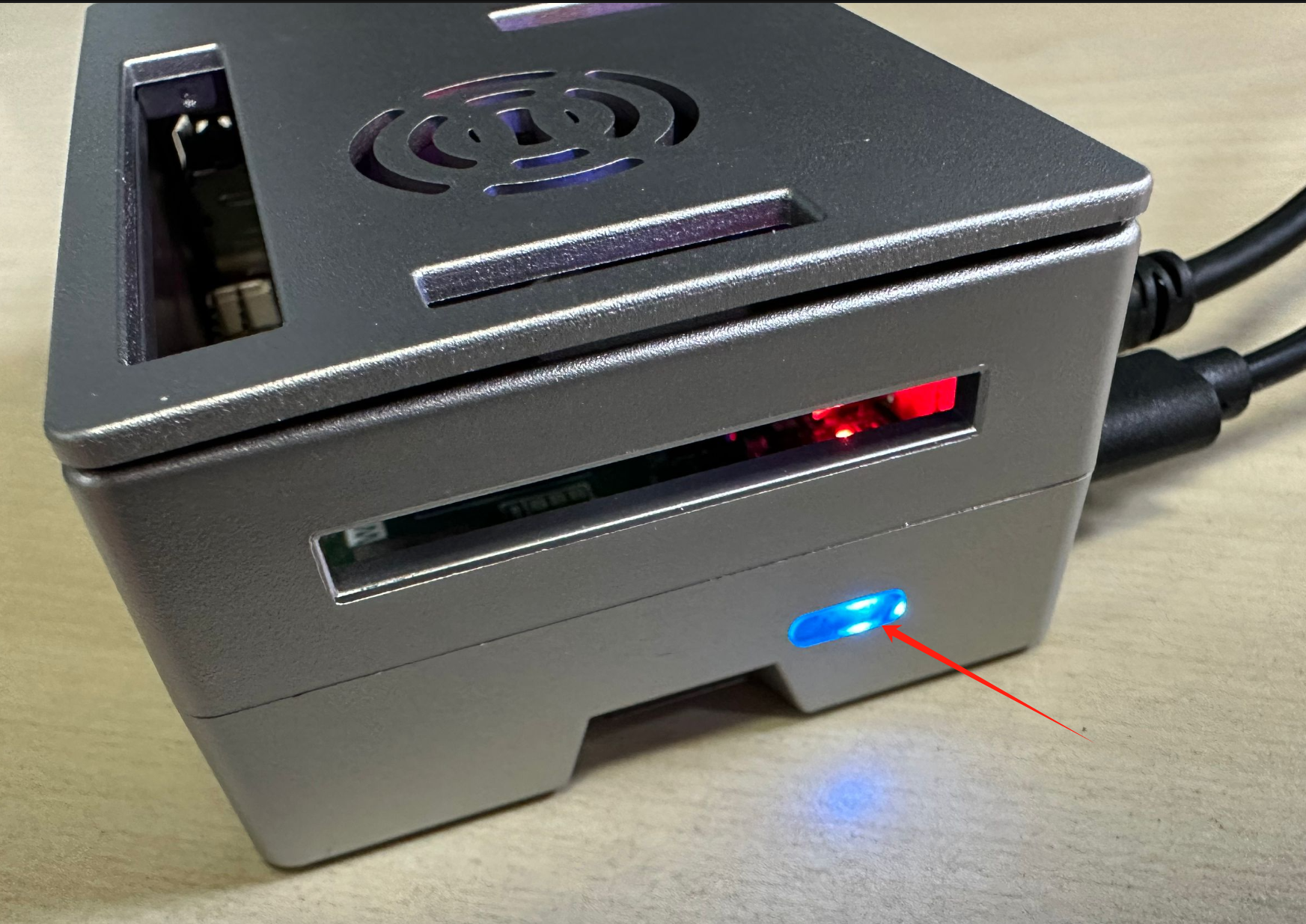
The LED light pipe and button are located in the position shown below. Test that the button works properly.
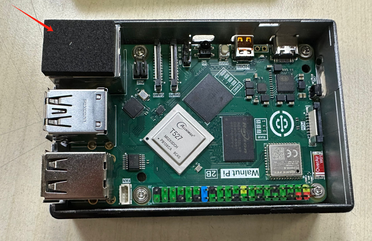
Open the top cover and panel, then place the included black pad at the Ethernet port position.
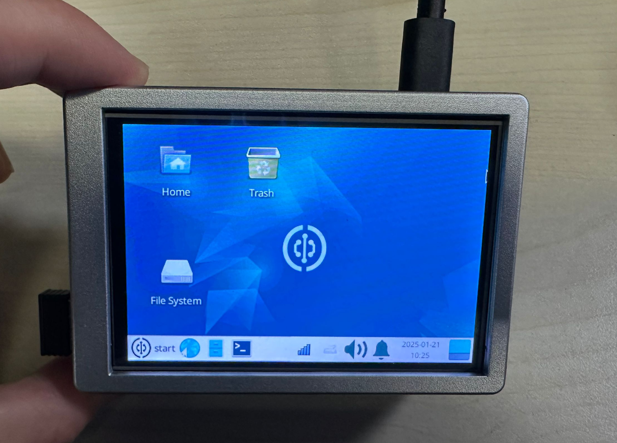
Insert the Walnut Pi 3.5-inch display, then close the case for use.
Acrylic Base Plate
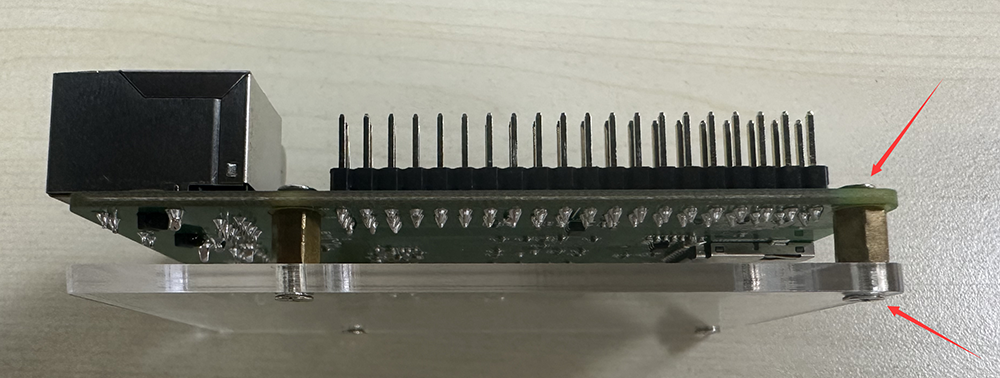
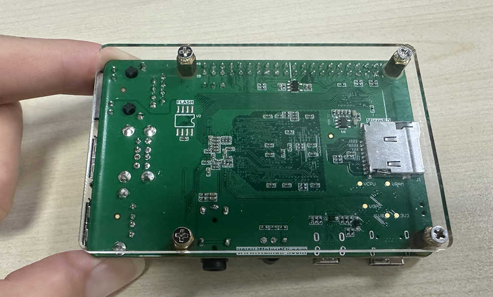
In addition to the case, you can also install just the acrylic base plate. The acrylic base plate prevents the PCB bottom from contacting metal objects and causing short circuits, protects the desktop from scratches, and creates an air gap underneath that improves heat dissipation.
The Walnut Pi acrylic base plate is very easy to install: peel off the protective film from the acrylic, place the copper standoffs in the middle, and tighten M2.5 screws at the top and bottom ends.
Power Connection
The Walnut Pi requires a power supply of 5V 3A or higher via a Type-C connector.
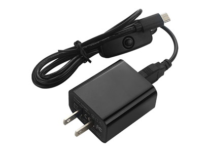
Connecting power is usually the final step—once powered on, we are ready to start using the board. Connect the Type-C end of the power cable to the Walnut Pi. If the cable has an inline switch, make sure to turn it on.
PoE (Power over Ethernet)
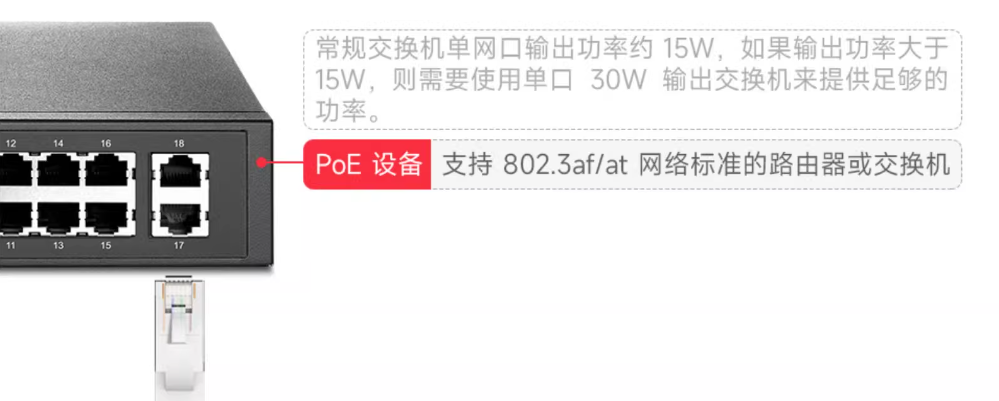
In addition to the Type-C power supply, the Walnut Pi 2B also supports PoE power delivery. With just a single Ethernet cable, you can achieve both networking and power. A PoE-capable switch and PoE module are required.
- PoE switch: Recommended purchase link
A single Walnut Pi 2B consumes approximately 10-15W. If you only need to power one Walnut Pi 2B, a switch with a total power rating above 15W is sufficient. For multiple devices, calculate the total accordingly.
- PoE HAT: Recommended purchase link
PoE HATs compatible with Raspberry Pi 5 are also compatible with the Walnut Pi 2B.