SPI
Configuring Pins
Finding SPI Pins on the Board
For easy lookup, we've added a feature to display functional pin positions. Run the following command to see how many SPI buses are available on the board's 40-pin header:
gpio pin spi
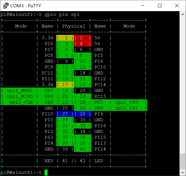
As shown, there is only spi1 on this 40-pin header, along with two CS pins belonging to spi1. A single SPI interface can be connected to multiple modules, with each module connected to a different CS pin. The CS pin determines which module to communicate with.
Enabling SPI-Dev
We use the set-device command to enable/disable the underlying driver for a specified device. Once enabled, the pins will switch from GPIO mode to their corresponding alternate function. (A reboot is required for the changes to take effect.)
To use spi1, first enable spi1, then enable a spidev1_x. For example, enabling spidev1_0 corresponds to spi1-cs0. After reboot, a /dev/spidev1.0 file will appear. When operating this file for SPI communication, it will automatically assert the spi1 cs0 pin (pull low) and deassert all other CS pins (pull high).
Note: Enabling spidev1_0 will cause all other device drivers using spi1-cs0 to become invalid, such as the 3.5-inch LCD screen.
Here I'm enabling spidev1_0. Note that a reboot is required for the changes to take effect:
sudo set-device enable spidev1_0
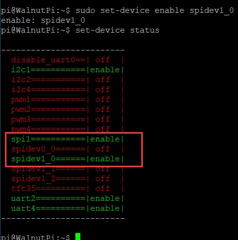
After reboot, you'll see that the /dev/spidev1.0 file has appeared, as we will need to operate this file for spi1_cs0 communication later:

SPI Read/Write Program
We need to operate the /dev/spidev1.0 file. Open it with open, configure and trigger SPI read/write with ioctl, and close it with close.
1. Opening the File
In Linux, everything is a file. First, use the open function to open the device file corresponding to the device we want to operate, obtaining a file descriptor.
The open function requires these header files:
#include <sys/types.h>
#include <sys/stat.h>
#include <fcntl.h>
#include <unistd.h>
Open the device node:
    int fd = open("/dev/spidev1.0", O_RDWR);
    if (fd < 0)
    {
        perror("Fail to Open\n");
        return -1;
    }
2. Configuring SPI Mode
SPI mode — depending on CPOL and CPHA, SPI is divided into 4 modes. Different chips may require you to operate in a specific mode.
The ioctl function requires these header files:
#include <sys/ioctl.h>
Configure for mode 0, i.e., CPOL=0, CPHA=0:
static uint32_t SPI_MODE = SPI_MODE_0;
    if (ioctl(fd, SPI_IOC_WR_MODE32, &SPI_MODE) == -1)
        printf("err: can't set spi mode");
3. SPI Transfer
The two SPI pins work simultaneously — MISO and MOSI operate synchronously. Use the spi_ioc_transfer structure to describe a single SPI transfer. SPI can be used to simulate many protocols, or rather, many chips claiming to have an SPI interface have quirky timings.
tx_buf: Buffer to send out via MOSIrx_buf: Buffer to store MISO datalen: Buffer sizespeed_hz: SPI transfer speedcs_change: Whether to keep the CS line asserted after the transfer completesbits_per_word: Size of each word during transferdelay_usecs: Delay after sendingtx_nbits: How many lines to use for SPI transmission. 4-line QSPI also uses this interface for transmission, so this option is provided for selection
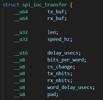
First, you'll need the following header file:
#include <linux/spi/spidev.h>
Here's an example:
static uint8_t BITS_PER_WORD = 8;
static uint32_t SPEED = 80 * 1000;
    transfer.tx_buf = (unsigned long)tx_buf;
    transfer.rx_buf = (unsigned long)rx_buf;
    transfer.len = len;
    transfer.delay_usecs = 500;     // Delay after sending
    transfer.speed_hz = SPEED;
    transfer.bits_per_word = BITS_PER_WORD;
    transfer.tx_nbits = 1;  // Single-line
    transfer.rx_nbits = 1;  // Single-line
    transfer.cs_change = 0; // Release CS line after transfer
Then use the ioctl function with SPI_IOC_MESSAGE(x) (where x = the number of transfers passed in) to trigger an SPI transfer. Each time a clock pulse is sent, the contents of tx_buf are output from MOSI while simultaneously reading MISO contents into rx_buf:
    int res = ioctl(fd, SPI_IOC_MESSAGE(1), &transfer);
    if (res < 0)
        printf("err: spi_transfer failed");
4. Closing the File
Remember to call close after each open to manually close the file. Otherwise, the file descriptor will remain open until the program exits. The system limits a single process to opening at most 1024 files at once. If a program continuously calls open without close, it won't be long before it errors out and exits.
close(fd);
Example Program
Here we use the MCP3004 ADC chip, which converts 4 analog input channels to SPI output. First, read the chip datasheet to understand the read procedure, as shown below:
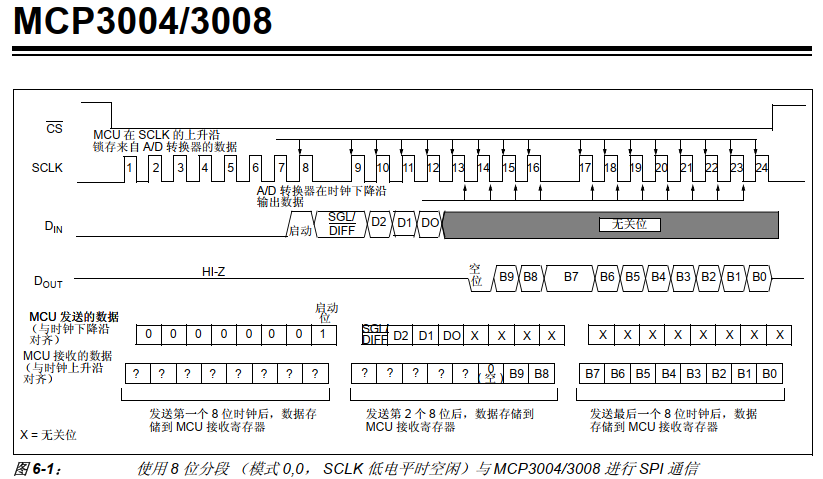
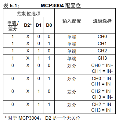
Now I want to read the value of channel 0. I need to send 3 bytes of data: the first byte is 0x01 as a start signal, the second byte is the configuration word 0x80, and the third byte has no function — it's only there to trigger reception. The code is as follows:
#include <stdio.h>
#include <stdint.h>

#include <sys/types.h>
#include <sys/stat.h>
#include <fcntl.h>
#include <unistd.h>

#include <sys/ioctl.h>

#include <linux/spi/spidev.h>

#define DEV_SPI "/dev/spidev1.0"

static uint32_t SPI_MODE = SPI_MODE_0;
static uint8_t BITS_PER_WORD = 8;
static uint32_t SPEED = 100 * 1000;

// MOSI and MISO work simultaneously — data is sent from tx_buf
// while at the same time data is read into rx_buf
int spi_transfer(int fd, uint8_t *tx_buf, uint8_t *rx_buf, int len)
{
    struct spi_ioc_transfer transfer;

    transfer.tx_buf = (unsigned long)tx_buf;
    transfer.rx_buf = (unsigned long)rx_buf;
    transfer.len = len;
    transfer.delay_usecs = 500; // Delay after sending
    transfer.speed_hz = SPEED;
    transfer.bits_per_word = BITS_PER_WORD;
    transfer.tx_nbits = 1;  // Single-line
    transfer.rx_nbits = 1;  // Single-line
    transfer.cs_change = 0; // Release CS line after transfer

    int res = ioctl(fd, SPI_IOC_MESSAGE(1), &transfer); // Trigger transfer
    if (res < 0)
        printf("err: spi_transfer failed");
    return res;
}

int main()
{
    int fd0 = open(DEV_SPI, O_RDWR);
    if (fd0 < 0)
    {
        perror("Fail to Open\n");
        return -1;
    }

    // Configure SPI mode
    if (ioctl(fd0, SPI_IOC_WR_MODE32, &SPI_MODE) == -1)
        printf("err: can't set spi mode");

    uint8_t tx_buf[3] = {0x01, 0x80, 0x00};
    uint8_t rx_buf[3];

    // MCP3004 requires the CS0 falling edge as the start of SPI communication
    // Since there's only one CS0 device under spi1, CS0 is initially low
    // Send one byte first to trigger CS0 high
    spi_transfer(fd0, tx_buf, rx_buf, 1);

    uint16_t value;
    while (1)
    {
        spi_transfer(fd0, tx_buf, rx_buf, 3);
        value = (rx_buf[1] << 8) + rx_buf[2];
        printf("value=%d\r\n ", value);
        sleep(1);
    }

    return 0;
}
Compiling on the board is straightforward. I've written the code in a file called spi.c. To compile it into an executable named exe, simply run:
gcc spi.c -o exe
The test result is shown below. As I turn the potentiometer connected to channel 0 of the MCP3004, the value changes accordingly:

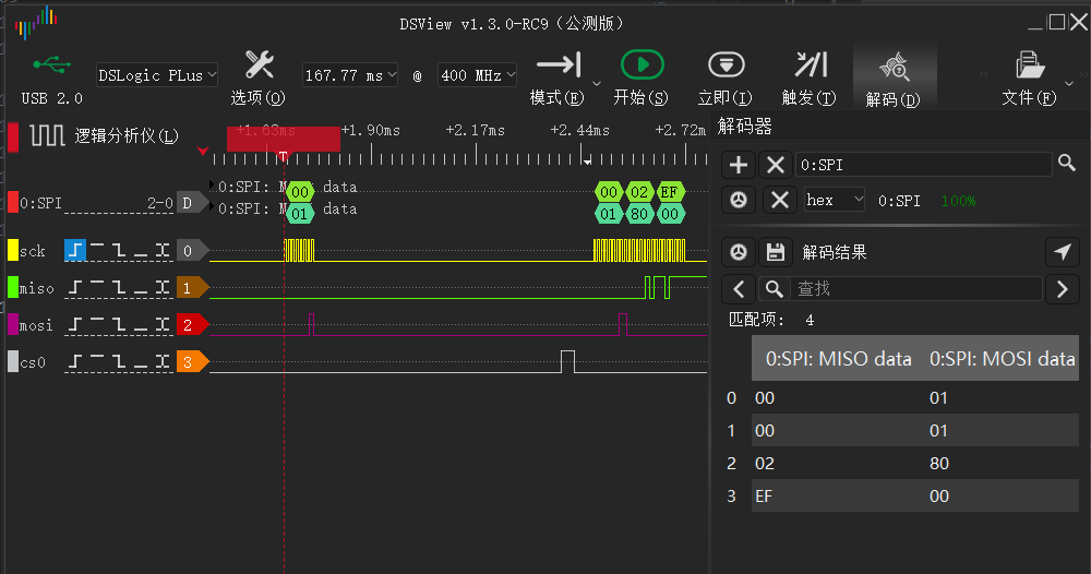
The initial timing when the code first runs is as follows: