WalnutPi ZeroW Peripheral Assembly
- Video Tutorial
After learning about WalnutPi's hardware in the previous section, we have a basic understanding of it. However, a single WalnutPi board cannot work on its own — it requires some essential peripherals, such as a power supply, keyboard, mouse, display, etc. In this section, we will introduce the WalnutPi ZeroW peripheral assembly in detail.
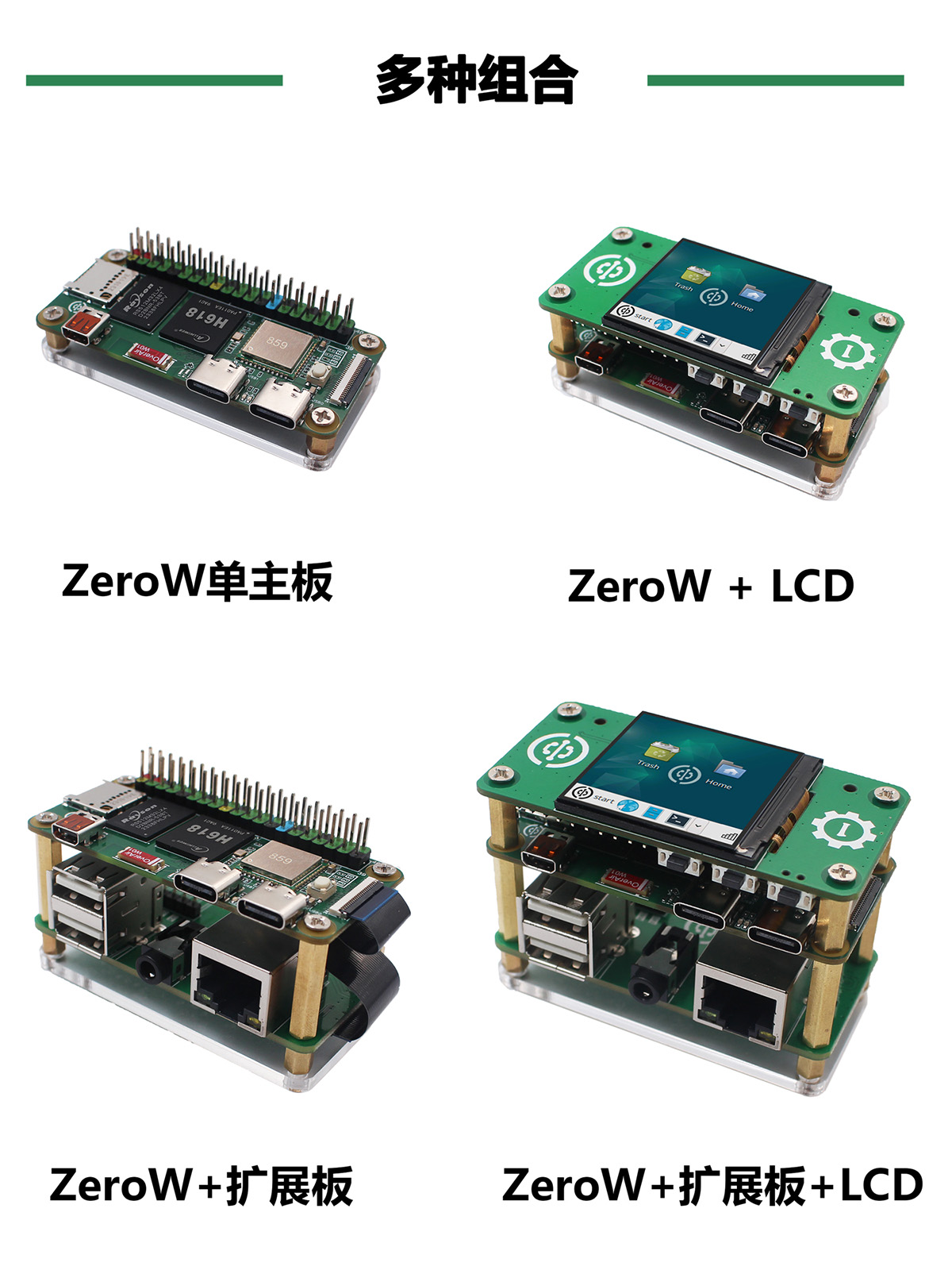
WalnutPi ZeroW, when paired with an expansion board and a 1.54-inch LCD, supports multiple usage scenarios.
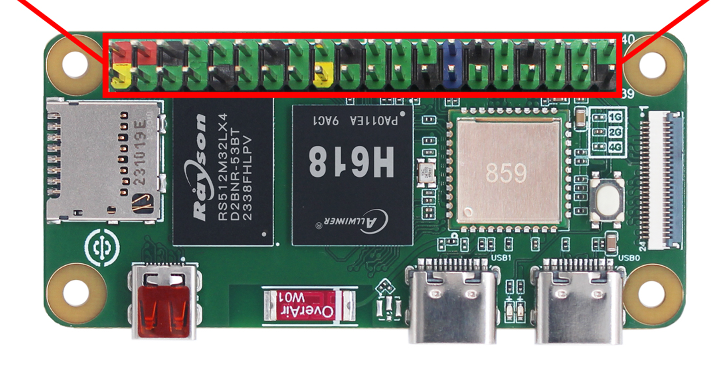
40-Pin Color Header
By default, WalnutPi ZeroW does not come with the 40-pin header soldered. Users need to pay attention to the orientation when soldering it themselves — it cannot be reversed. The soldering direction is as follows:
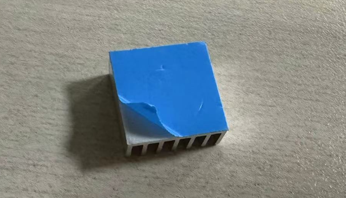
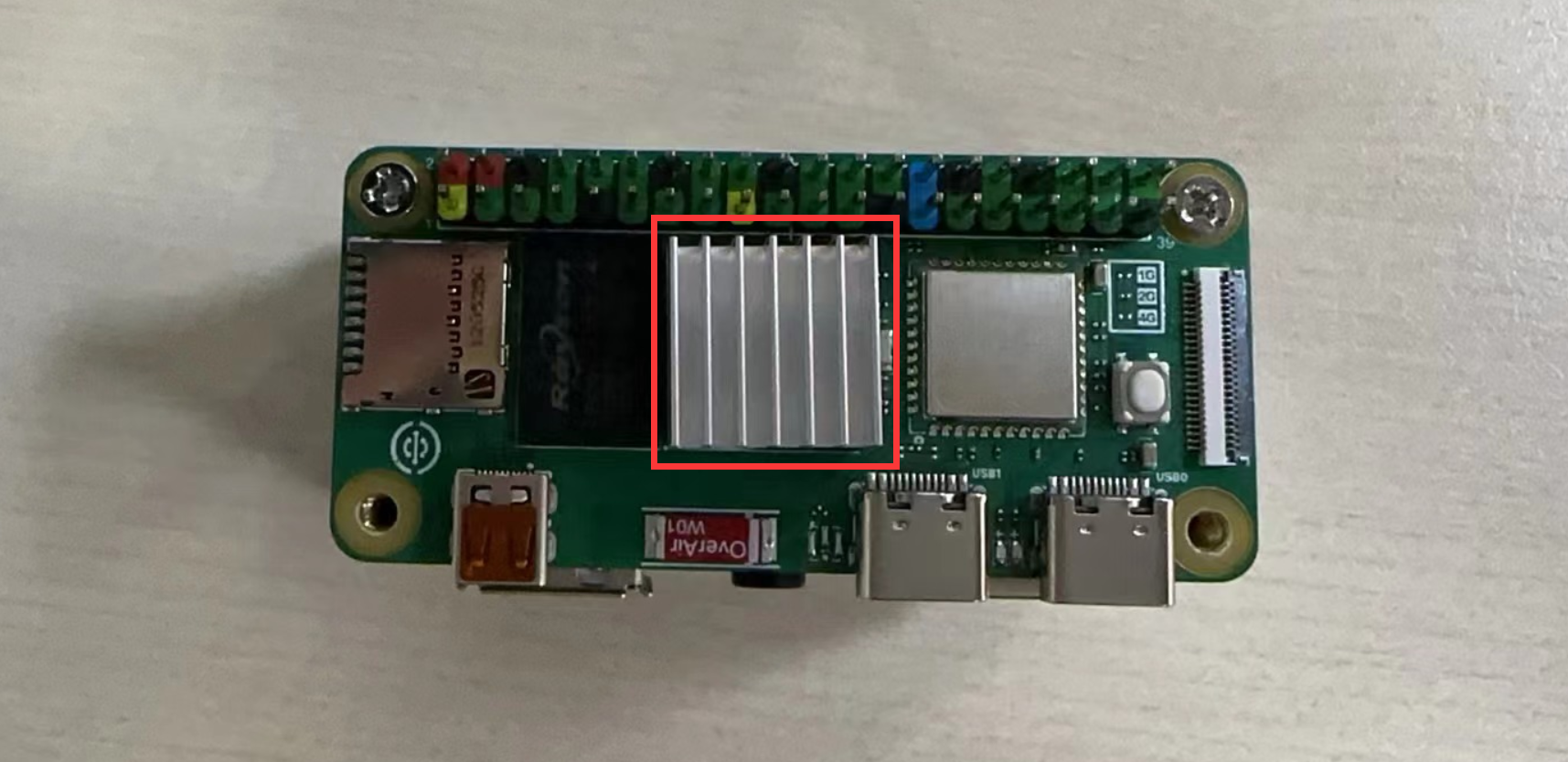
Heat Sink
The heat sink helps cool the WalnutPi CPU, ensuring stable operation especially in high-temperature environments. Installation is also simple: peel off the thermal pad and stick it onto the SoC. Since the heat sink is conductive, be careful not to let it touch other components on the circuit board (capacitors, resistors) during installation to avoid short circuits. (ZeroW is compact, so adding a heat sink for auxiliary cooling is recommended.)
Acrylic
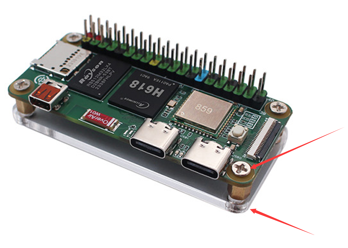
The acrylic base plate prevents the bottom of the PCB from short-circuiting with other metal objects, protects the desktop from scratches, and the space created underneath also improves heat dissipation.
Installing the WalnutPi ZeroW acrylic base plate is very simple: peel off the acrylic protective film, insert copper standoffs in the middle, and tighten both top and bottom with M2.5 screws.
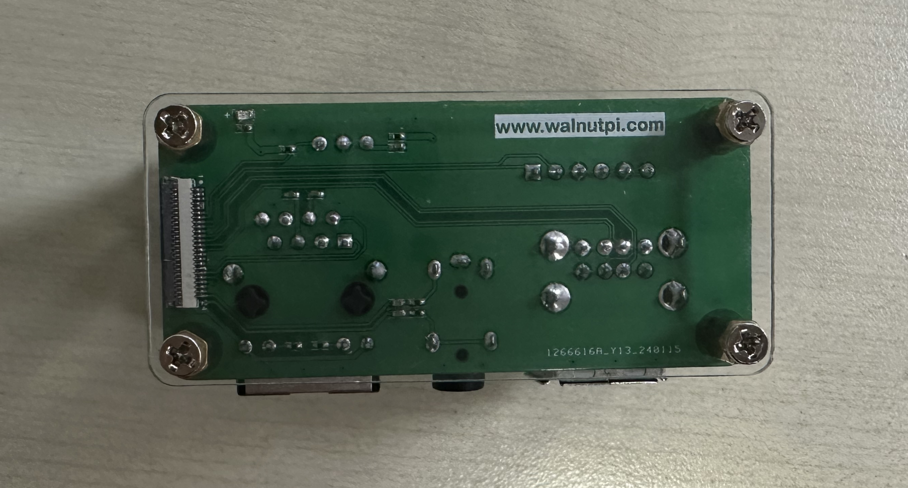
ZeroW Expansion Board
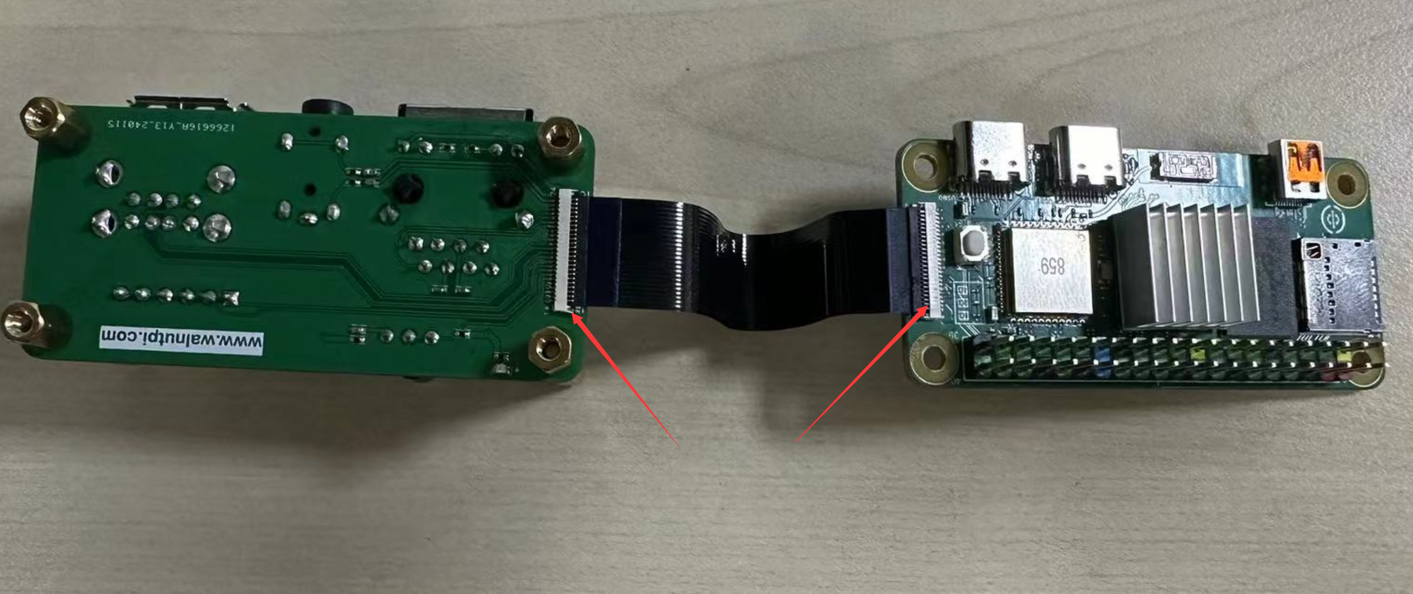
The WalnutPi ZeroW expansion board connects to the WalnutPi ZeroW mainboard via a 24-pin 0.5mm FFC cable, providing USB 2.0 x2, 100Mbps Ethernet, audio, IR receiver, debug serial port, and 5V/3.3V power output.
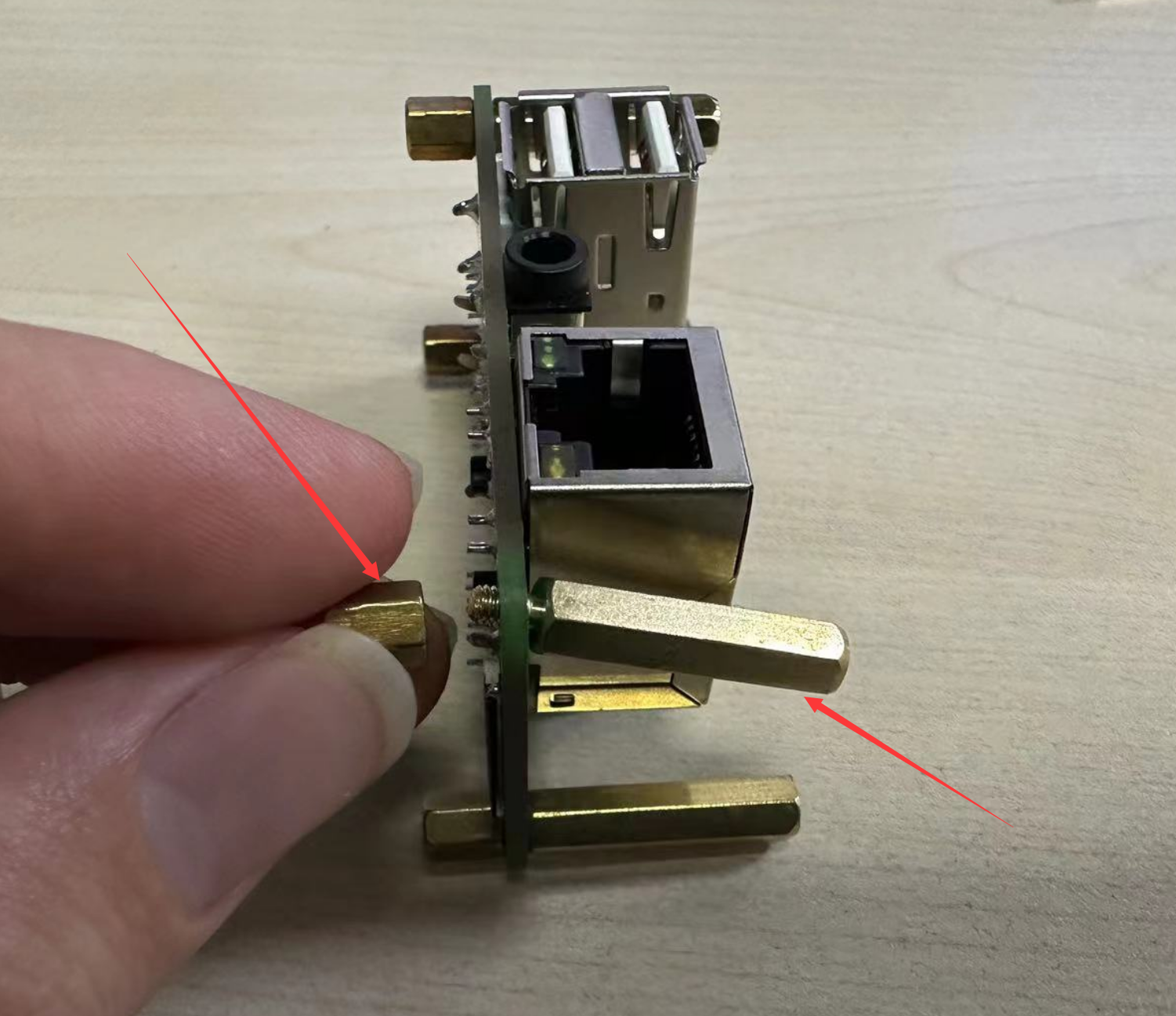
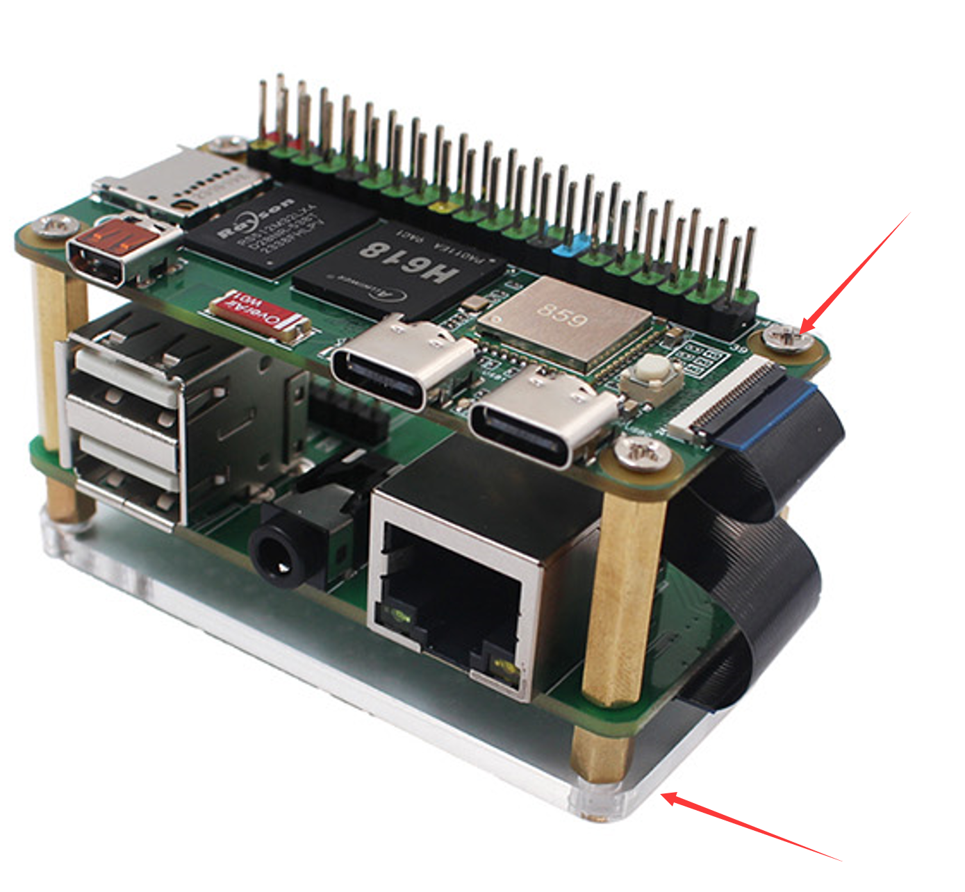
Connect using 20mm single-threaded standoffs and 6mm double-threaded standoffs as shown below:
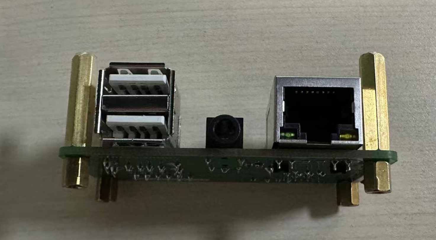
Use the FFC cable to connect ZeroW and the expansion board. Note that the gold finger contact side should face downward when inserting:
Then use M2.5 screws to secure both the ZeroW and the acrylic base plate from above and below.
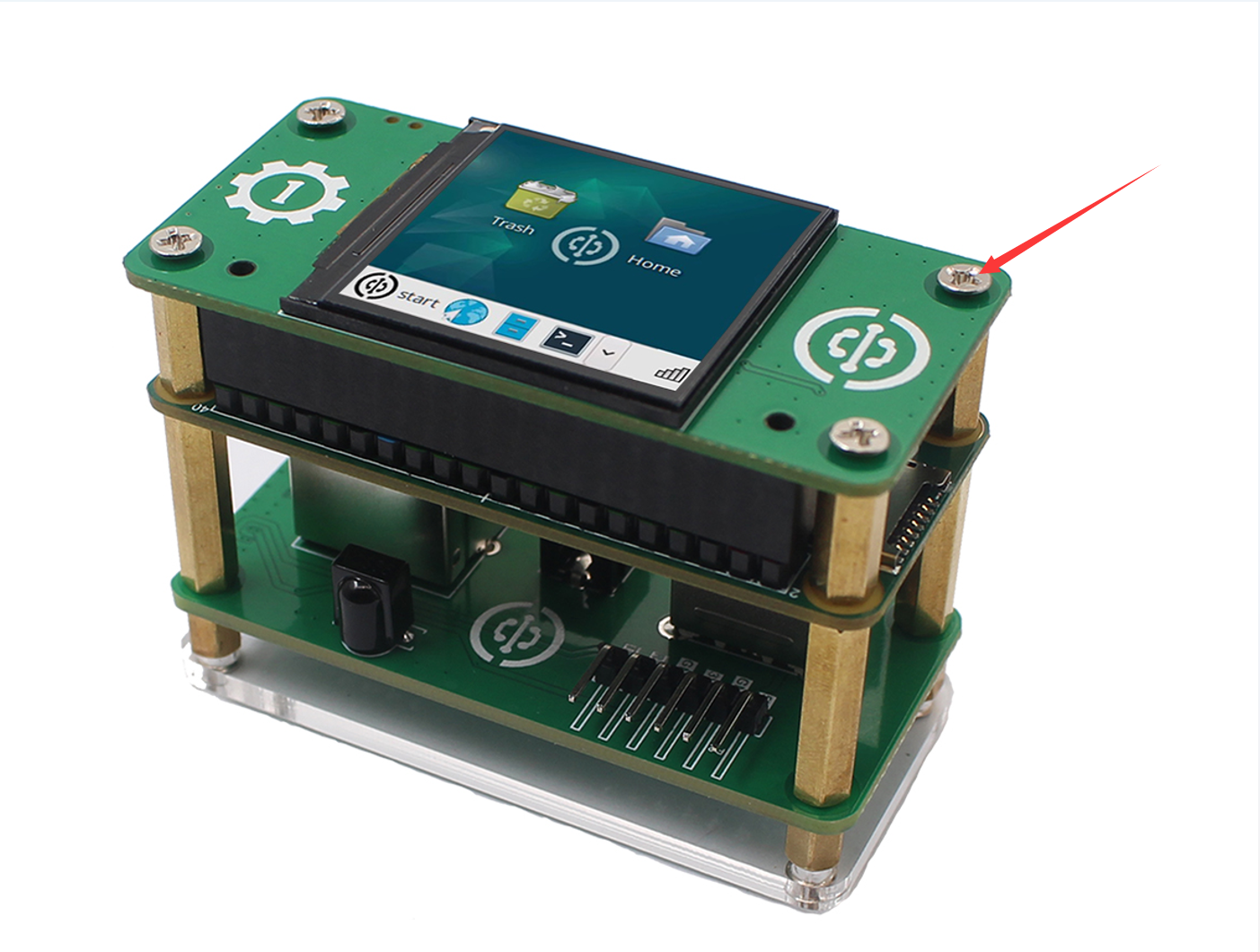
1.54-inch LCD
Insert the 1.54-inch LCD directly into the interface as shown below. For easier insertion and removal, you can skip the standoffs.
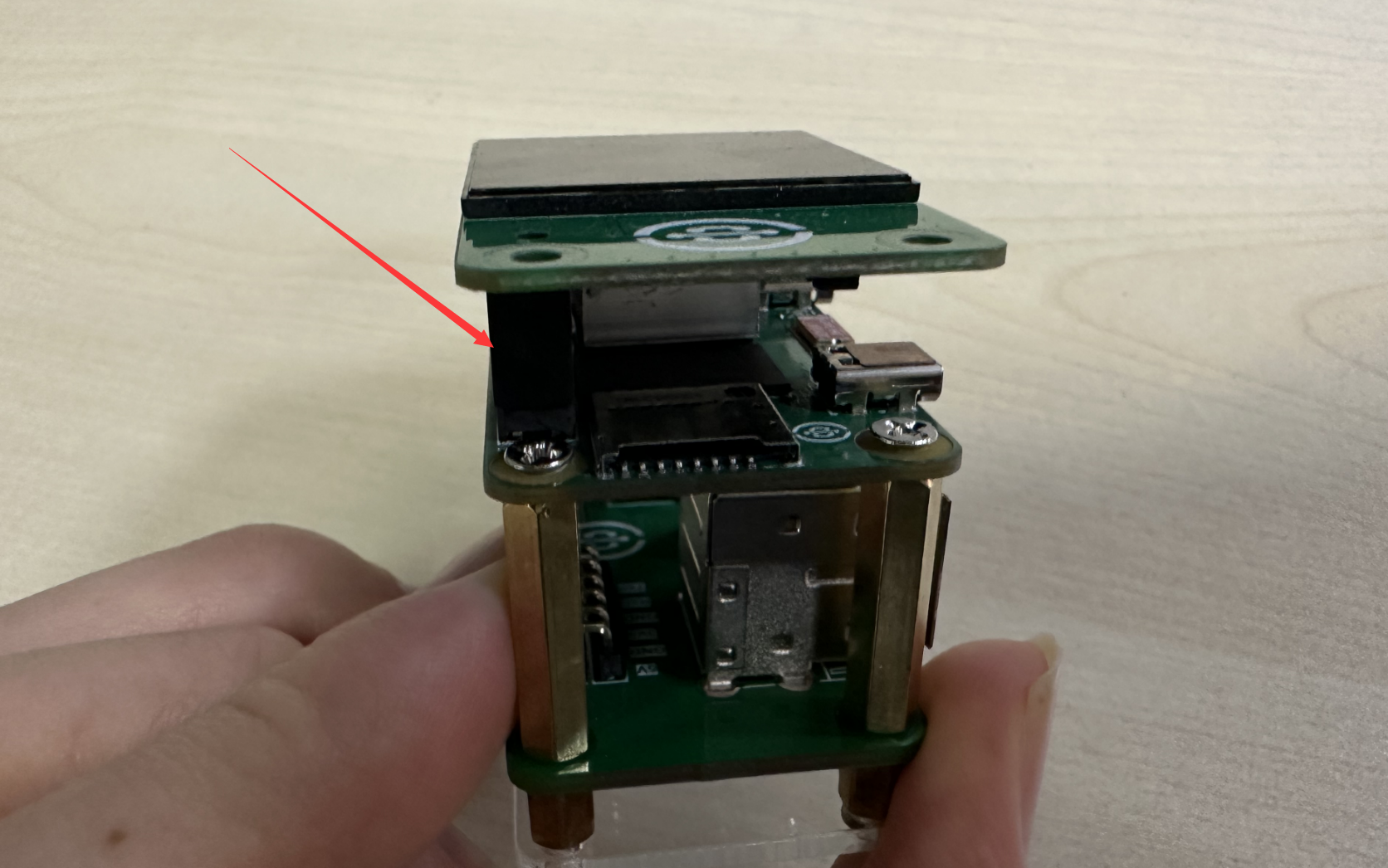
If you need to secure it, use the included 12mm single-threaded copper standoffs:
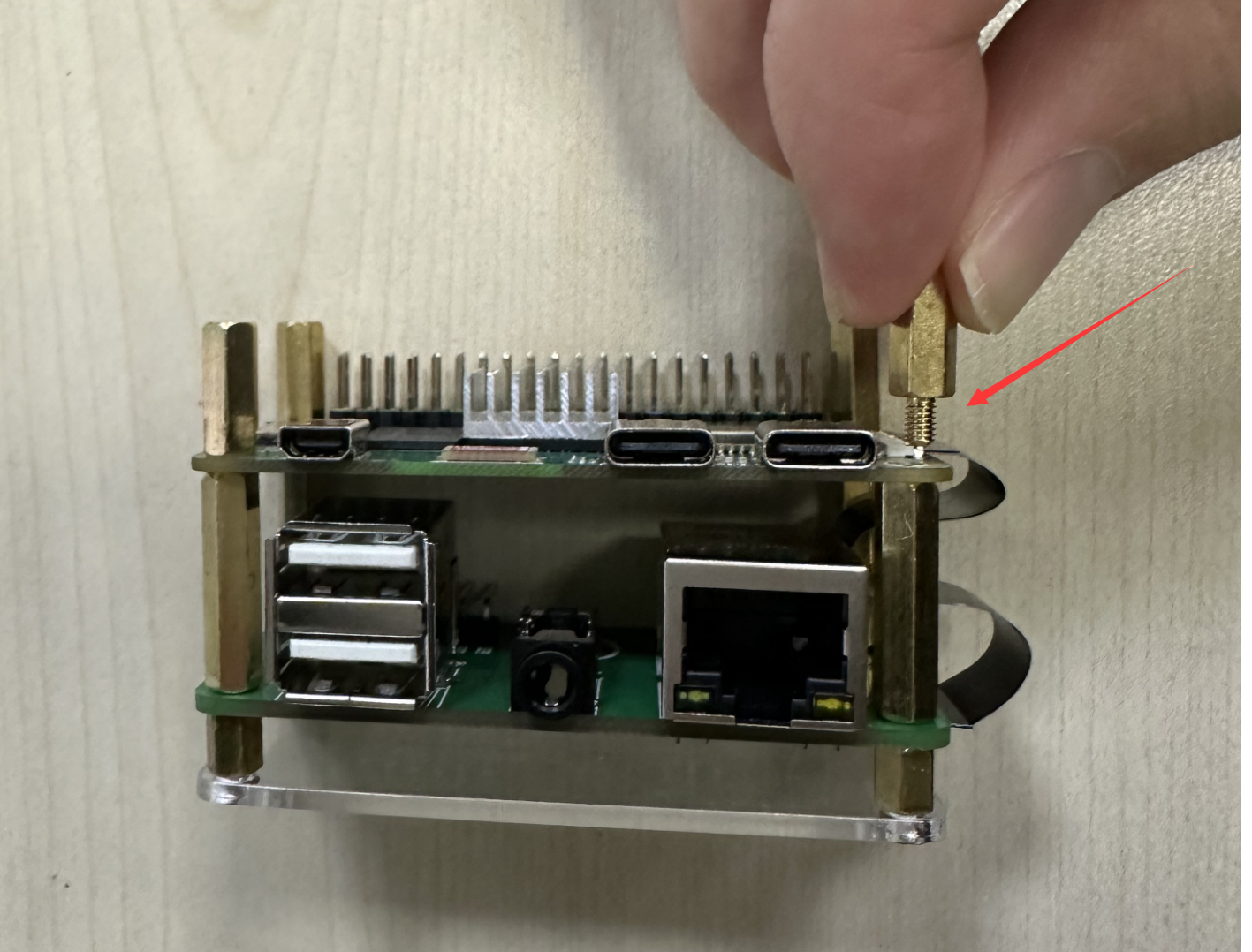
Insert the 1.54-inch LCD and secure the top with M2.5 screws:
MicroSD Card
The MicroSD card needs to have the operating system copied onto it in advance. This will be covered in detail in the next section on system and software. Here we only introduce the installation method. A MicroSD card of 16GB or larger is recommended.
Gently insert the MicroSD card all the way in as shown below. WalnutPi ZeroW's MicroSD card slot is a push-pull type without a self-eject mechanism.
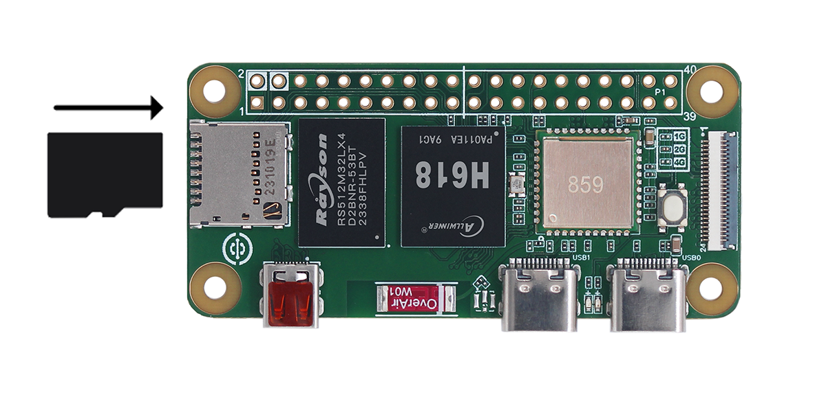
If you need to remove the SD card, simply pull it outward.
Do not insert or remove the SD card while the device is powered on.
USB Hub
Both Type-C ports on WalnutPi ZeroW support USB hub expansion, making it convenient to connect USB cameras, USB keyboards, mice, and other devices:
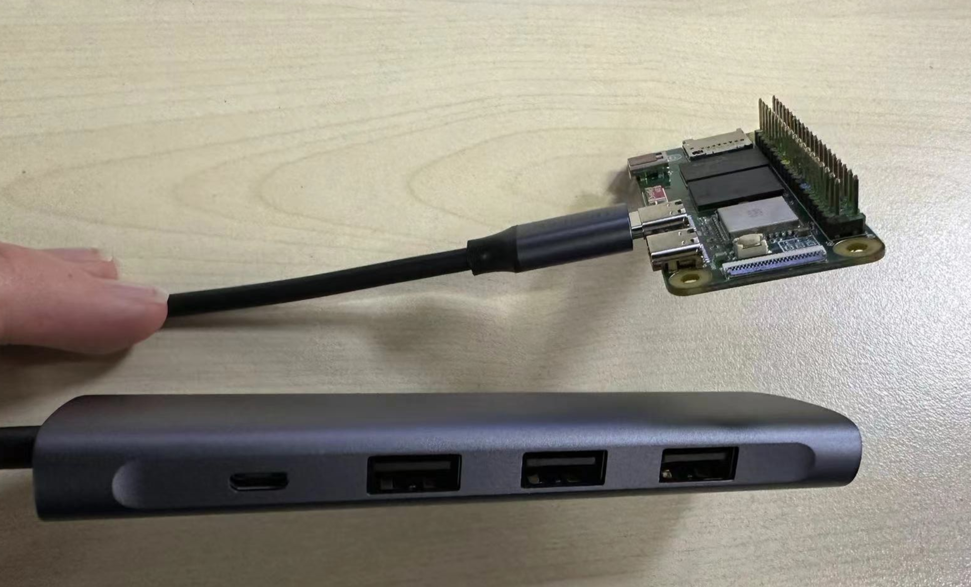
USB hubs are only tested to support USB expansion. Some Type-C to HDMI features may not work due to driver issues.
Keyboard and Mouse
WalnutPi supports both wired and wireless keyboards and mice.
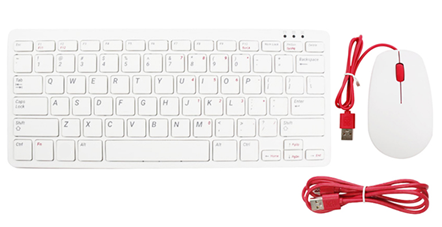
Wired Keyboard & Mouse
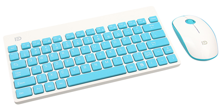
Wireless Keyboard & Mouse
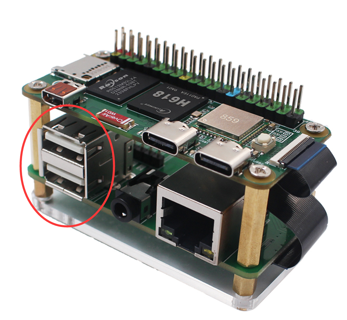
Connect the keyboard and mouse to the expansion board USB port. The installation method for wired and wireless USB keyboards and mice is the same. Under normal circumstances, plugging and unplugging USB devices should not require much force — if it feels difficult, the connector may be upside down. Check that the USB orientation is correct.
Display
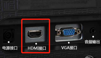
Most computer monitors or TVs come with an HDMI port.
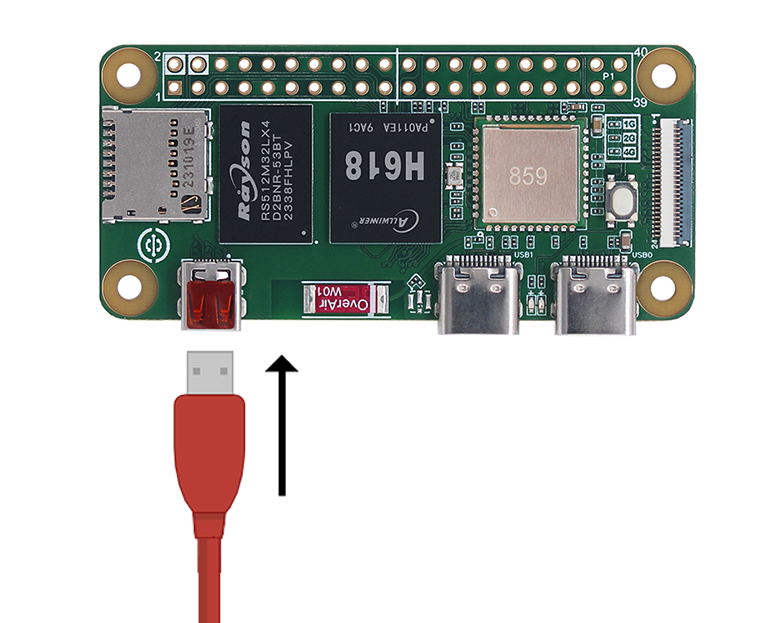
Using a micro-HDMI to HDMI cable, you can directly output WalnutPi's video signal to a display.
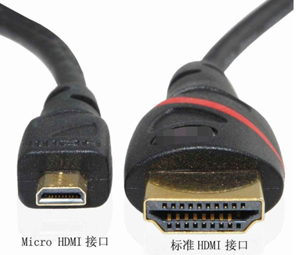
Connect the smaller end of the micro-HDMI cable to WalnutPi (the small port near the ceramic antenna), and the other end to the display. If your display has multiple input ports, you may need to switch input sources — this depends on your specific display.
Ethernet Cable
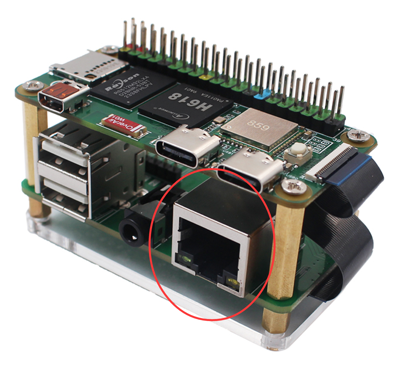
To connect WalnutPi to a network, you can use either Ethernet or WiFi wireless. WiFi is commonly used, and WalnutPi's WiFi supports 5G connections. Here we mainly explain how to connect the Ethernet cable. Insert it into the Ethernet port with the plastic clip facing down until you hear a click. The other end of the cable is typically connected in the same way to any available port on a router, network hub, or switch. If you need to remove the cable, simply squeeze the plastic clip inward toward the plug and gently slide the cable out. (The Ethernet port is on the expansion board and is a 100Mbps port.)
Audio
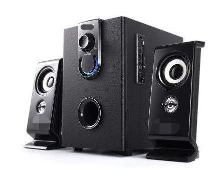
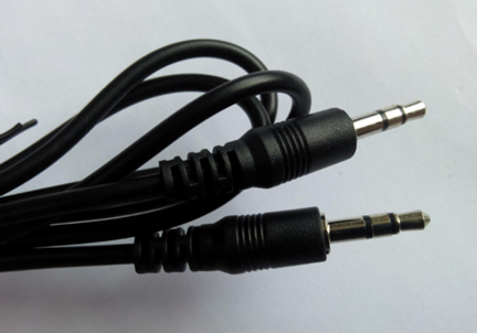
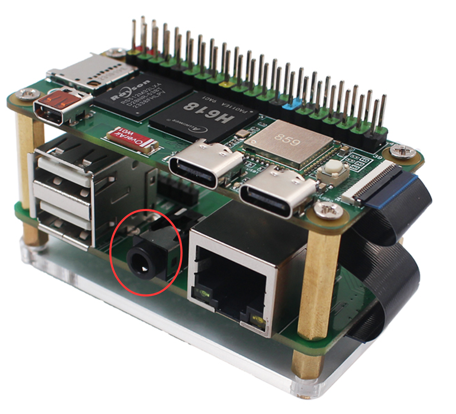
The WalnutPi expansion board has a standard 3.5mm audio output jack. You can connect headphones or speaker devices for audio playback.
Power Connection
The power requirement for WalnutPi ZeroW is: a Type-C power supply of 5V 1A or above.
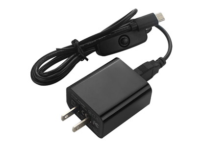
Connecting power is usually the final step — once powered on, it means we are ready to start using it. Connect the Type-C end of the power supply to WalnutPi. If the cable has a switch, remember to turn the switch on.
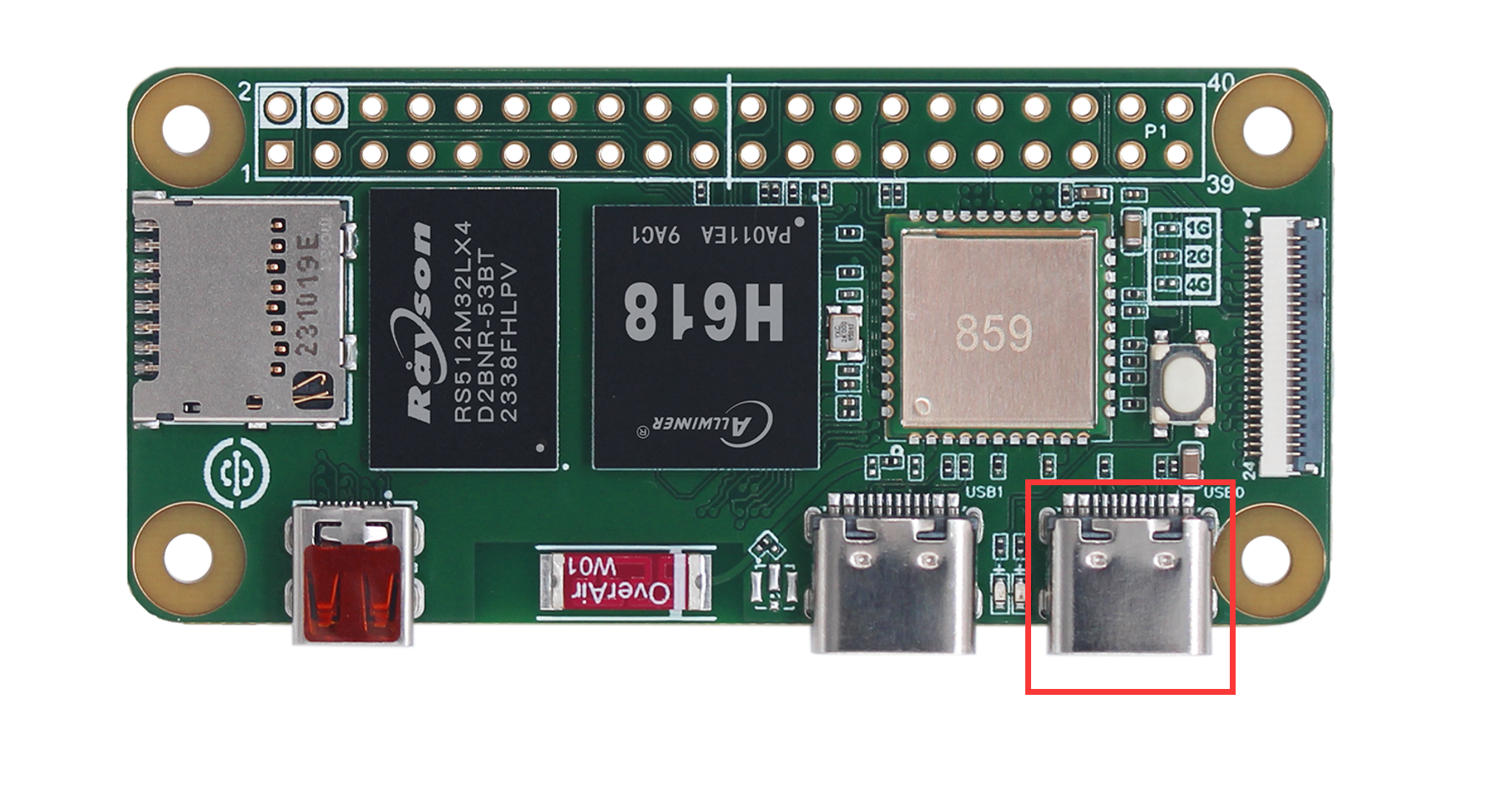
Both Type-C ports on WalnutPi ZeroW can be used as power input. The right-side port is typically used:
At this point, the WalnutPi ZeroW peripheral assembly is complete.