GPIO Command-Line Operations
We provide a set of commands for quickly operating GPIO from the command line. This section mainly introduces how to use these commands.
To control GPIO using Python programming, please refer to this section: Python Embedded Programming - Lighting the First LED
To control GPIO using C programming, please refer to this section: C Embedded Programming - Controlling GPIO
Starting from WalnutPi system v2.3, WiringPi-based pin numbering has been deprecated in favor of using header pin numbers to reference pins.
View All Pin Statuses
Use the following command to see all pin definitions on the WalnutPi:
gpio readall
or
gpio pins
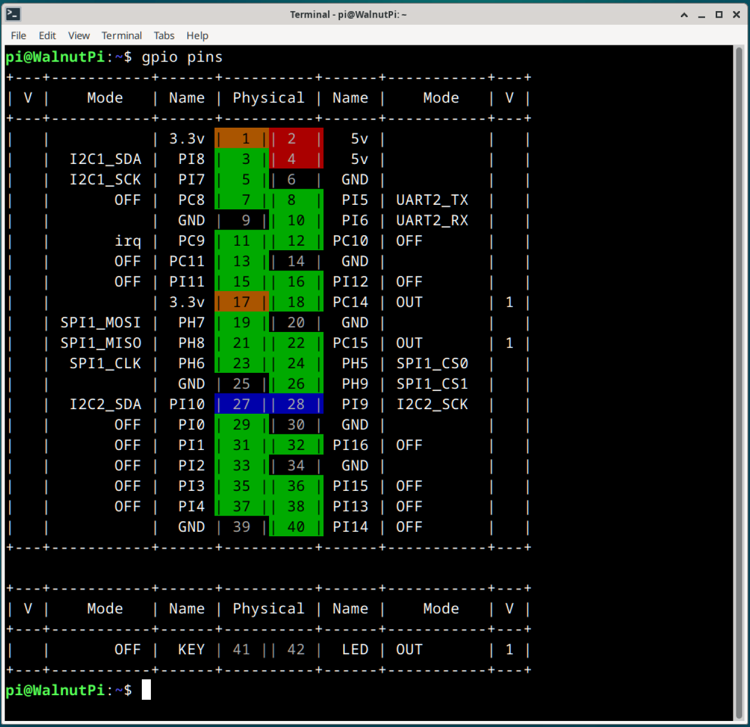
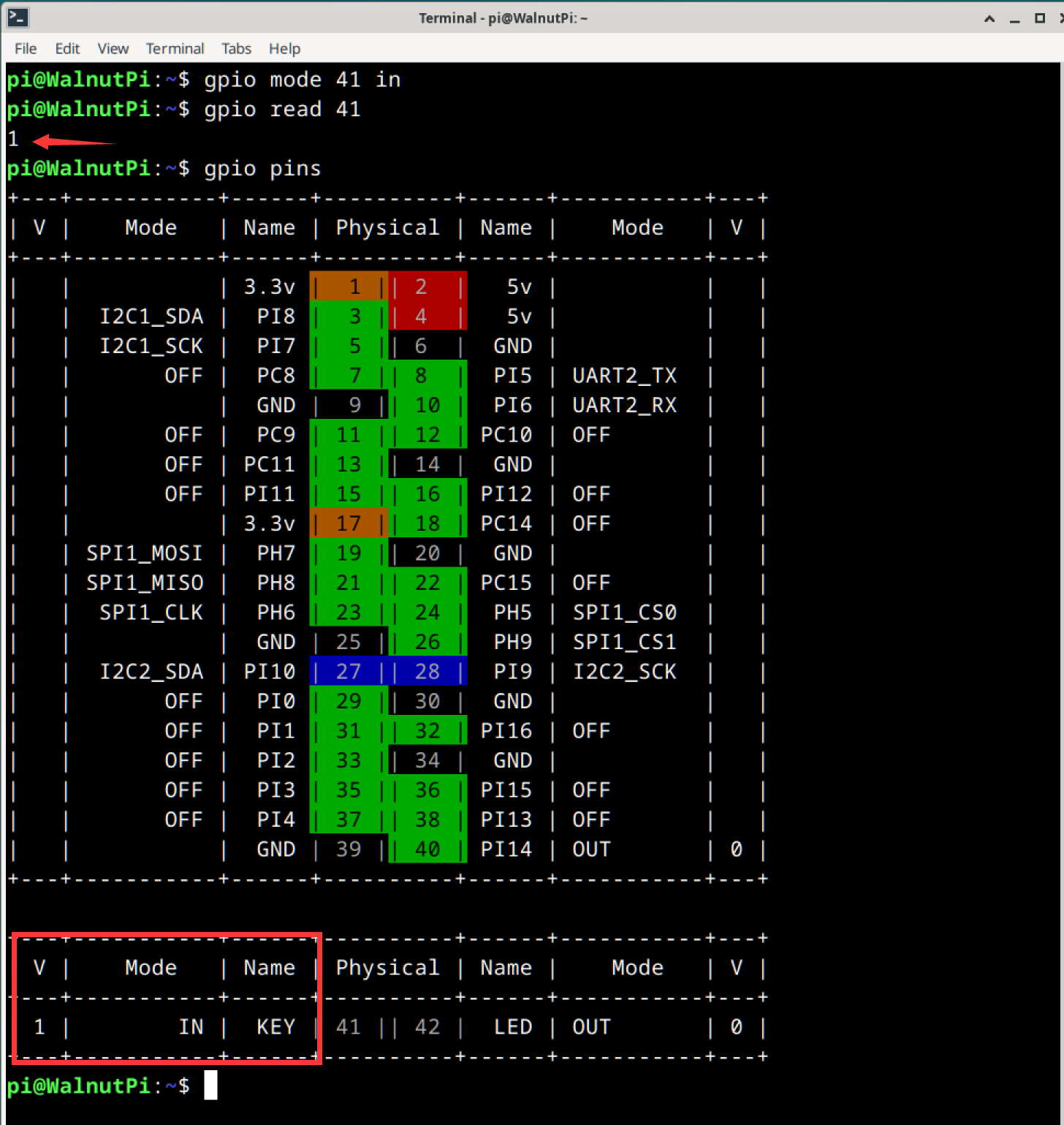
The columns in the table above are defined as follows:
Physical: The header pin number on the board, used for all subsequent command operationsName: Pin name, which can be used when programming in Pythonmode: The current operating mode of the pin:OFF: Initial state, not configuredIN: Input modeOUT: Output modeOther: Alternate function
V: When the pin is in IN/OUT mode, the logic level of the pin. 1 is HIGH, 0 is LOW
Locate I2C/UART/SPI Pins
This is a WalnutPi-specific feature for user convenience.
gpio pin [function]
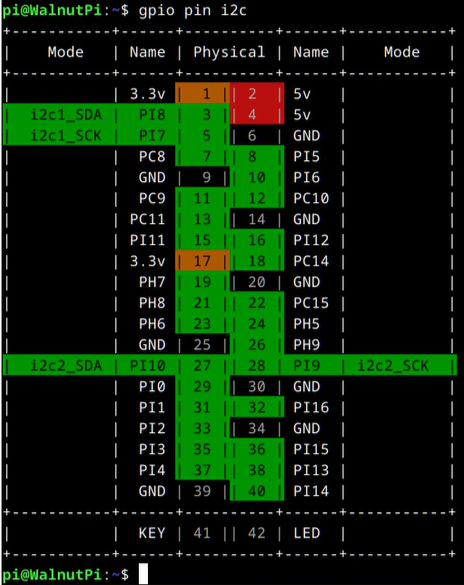
This outputs a table showing the positions of pins with the specified function.
[function]: Function type, choose from the following options:pwmuartspii2c
For example, to find out which pins are I2C pins, enter the following command:
gpio pin i2c
Set Pin Mode
gpio mode [PIN] [mode]
[PIN]: The target pin's header number[mode]: Choose from the following:IN: Input mode, floatingIN_PULLUP: Input mode, with internal pull-up enabledIN_PULLDOWN: Input mode, with internal pull-down enabledOUT: Output modeOFF: Return to the initial unused state
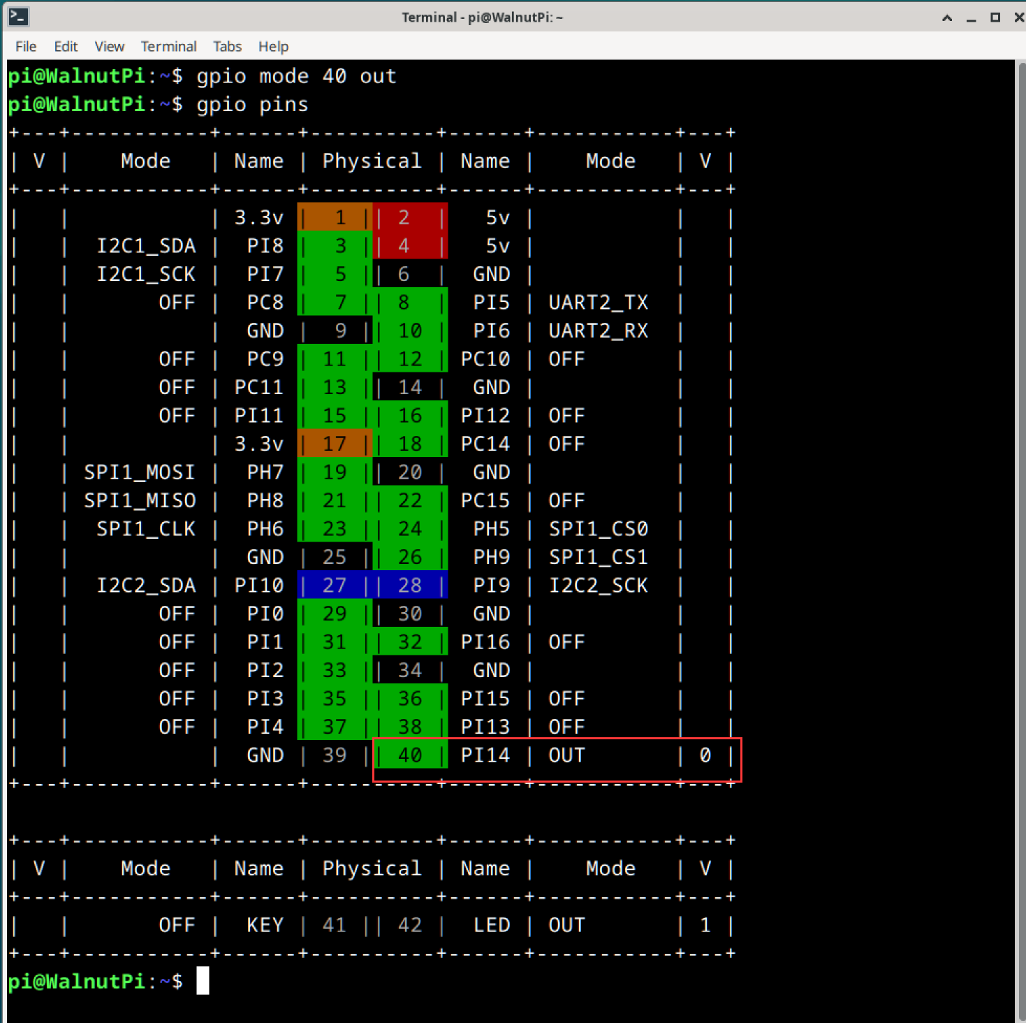
For example, to set pin 40 to output mode, use the following command:
gpio mode 40 out
After configuration, use the gpio pins command to verify the pin status. You will see that pin PC8's mode has been changed to OUT.
Control Pin Output Level
gpio write [PIN] [status]
[PIN]is the wPi number of the pin you want to control.[status]: Pin output state.0: LOW (0V)1: HIGH (3.3V)
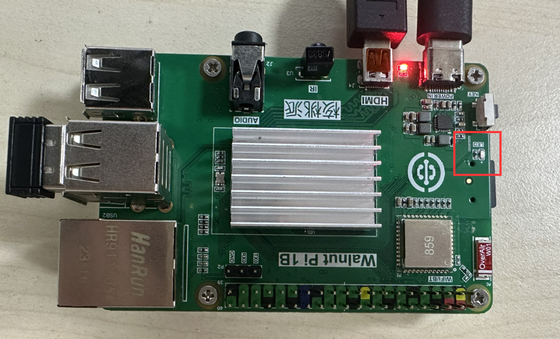
We can test this using the onboard blue LED. Since the LED is on by default after booting, let's turn it off with a command.
From the earlier table, we can see that the LED's pin number is 42. First, set the LED pin mode to output:
gpio mode 42 out
Then set the output state to 0 (LOW, 0V):
gpio write 42 0
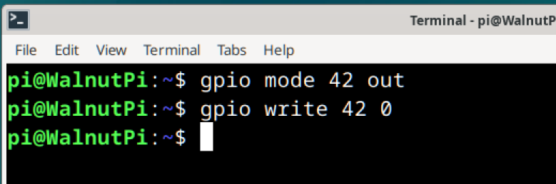
You can see that the blue LED on the WalnutPi has turned off.
Read Pin Input Level
gpio read [PIN]
[PIN]: The number of the pin to read.
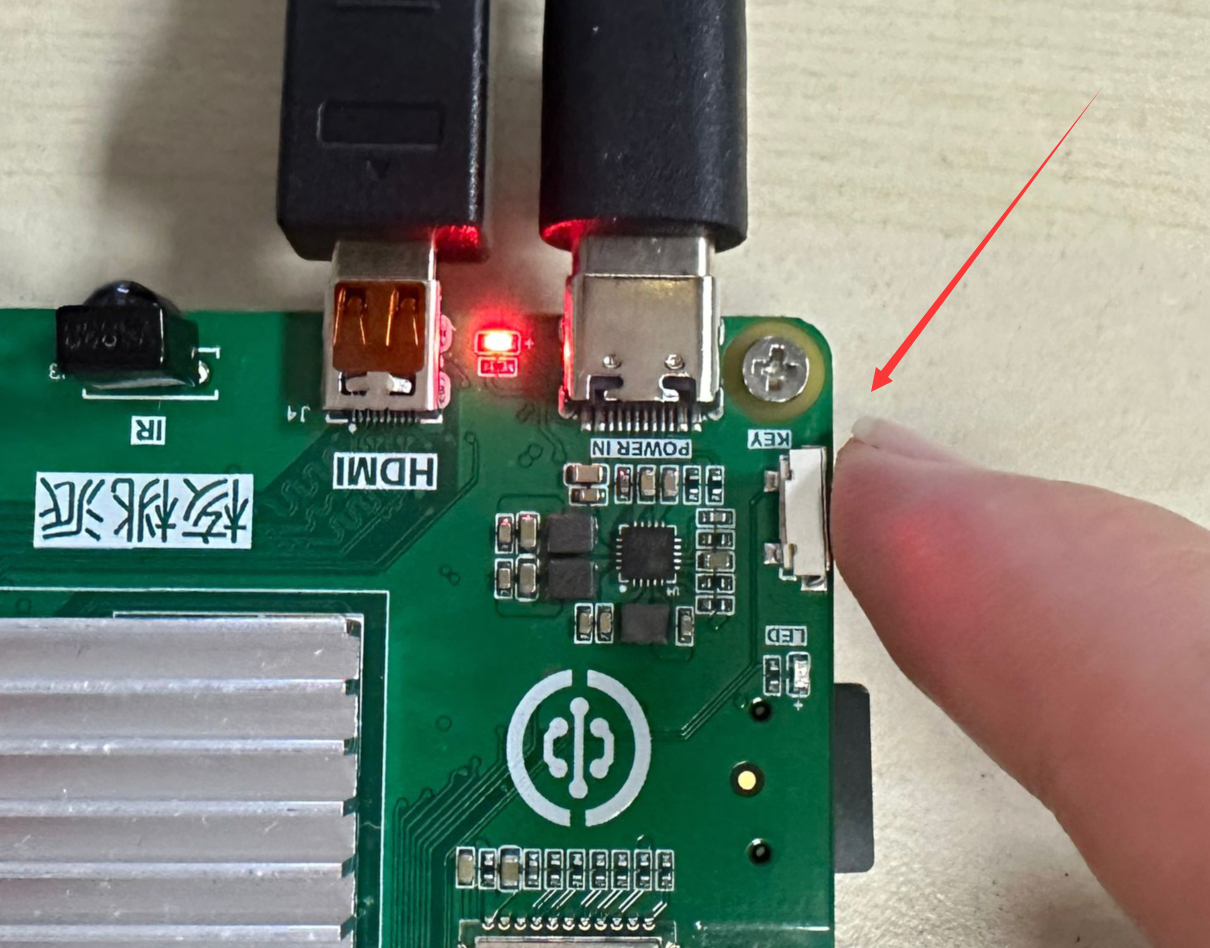
We can test this using the onboard button, reading its input level. When the WalnutPi's onboard button is not pressed, it reads 1 (HIGH, 3.3V); when pressed, it reads 0 (LOW, 0V).
From the earlier table, we can see that the KEY button's wPi number is 41. Since the board already has a pull-up resistor, we only need to set the KEY pin mode to input:
gpio mode 41 in
First, read the current voltage state of the button:
gpio read 41
You can see that the KEY pin's state is IN (input). Because of the pull-up resistor, when the button is not pressed, the pin's input level is 1 (HIGH, 3.3V).
Next, press and hold the button:
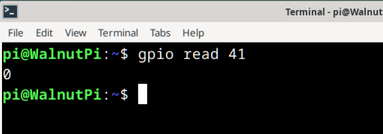
Then execute the read level command again. Because the switch is connected to ground, it pulls the pin level low, so you will see the input level change to 0 (LOW, 0V).
gpio read 41
Toggle Pin Output Level
This function toggles the output level of a pin in output mode. For example, if the pin is currently outputting HIGH, executing this command will switch it to LOW, and executing it again will toggle it back to HIGH.
gpio toggle [PIN]
[PIN]: The wPi number of the output pin.
For example, to toggle the onboard LED output state:
gpio toggle 42